Rotational Inertia
Source: Nicholas Timmons, Asantha Cooray, PhD, Department of Physics & Astronomy, School of Physical Sciences, University of California, Irvine, CA
Inertia is the resistance of an object to being accelerated. In linear kinematics, this concept is directly related to the mass of an object. The more massive an object, the more force is required to accelerate that object. This is seen directly in Newton's second law, which states that force is equal to mass times acceleration.
For rotation, there is a similar concept called rotational inertia. In this case, rotational inertia is the resistance of an object to being rotationally accelerated. Rotational inertia is dependent not only upon mass, but also upon the distance of mass from the center of rotation.
The goal of this experiment is to measure the rotational inertia of two rotating masses and to determine the dependence upon mass and distance from the axis of rotation.
A certain object or system of objects has some rotational inertia. The rotational inertia about a certain axis is called the moment of inertia. Because the distance from the mass to the axis of rotation is important, a single object can have very different moments of inertia depending upon the axis about which it rotates. The moment of inertia for an object is defined as:
 , (Equation 1)
where i is the number of objects.
In Equation 1, r is the distance from the axis of rotation to the mass. As can be seen in the equation, the moment of inertia is dependent upon the mass of the object and the square of the distance from the mass to the axis of rotation.
Just like how linear kinematics has equations of motion, rotational kinematics has analogous equations of motion. For example, Newton's second law for linear motion is:
 . (Equation 2)
A similar rotational equation takes the form:
 , (Equation 3)
where  is the torque,
  is the moment of inertia, and
  is the angular acceleration. Here, the moment of inertia is the analog of the mass term in Newton's second law. Similarly, the moment of inertia is present in the other important equations of rotational motion:
 , (Equation 4)
 , (Equation 5)
where  is the angular velocity of the object.
For this experiment, a mass is connected to a rotating arm by a string wound around the axis of rotation. See Figure 1 for an image of what the experimental setup looks like. Two masses will be connected to the rotating arm, friction will be ignored in this experiment, and the total moment of inertia will be equal to the moment of the rotating masses plus the moment of the spinning arm.
The mass, which falls due to the influence of gravity, will enact a torque on the rotating arm. From Equation 2, and  . Here,
  is the force on the object, which comes from the tension
  in the string, and
  is the distance from the force to the axis of rotation. Here, that distance is the distance from the edge of the wound string to the axis of rotation.
The angular acceleration is defined by  , where is the linear acceleration of a point on the wound string that corresponds to the acceleration of the falling weight. Putting everything together gives
  . Newton's second law is used to find the tension. The sum of the forces on the object should be equal to the mass times the acceleration. Here, the forces on the falling weight are gravity (
 ) and the tension , so
 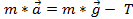 . Assuming a constant acceleration, then
  , where
  is the distance the weight travels and
  is the time it takes to fall that distance. This comes from the kinematic equations of motion.
Putting everything together results in an equation for the moment of inertia in terms of quantities that are measurable during the experiment:
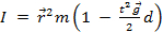 . (Equation 7)
If two masses are attached to the spinning arm at equal distances ![]() from the axis of rotation, then the moment of inertia will be:
from the axis of rotation, then the moment of inertia will be:
 , (Equation 8)
which is the theoretical value for this experiment.
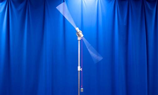
Figure 1. Experimental setup.
1. Measure the moment of inertia of the long rod.
- Wind the string attached to the weight until the weight is near the spinning arm.
- Drop the weight and measure the time it takes to drop, as well as the distance it drops.
- Perform step 1.2 three times and calculate the average moment of inertia using Equation 7.
- Compute the theoretical moment of inertia of the spinning rod using the following formula:
 , where
  is the mass of the rod and
  is the length.
 - Compare the theoretical value with the measured value and record the difference.
2. Two masses attached to the rod.
- Place two 100-kg masses 20 cm away from the center of the rod.
- Repeat steps 1.2 and 1.3 with the attached masses.
- The total moment of inertia should be equal to the moment of inertia of the attached masses plus the moment of inertia of the rod. Use this fact, the results from step 1, and Equation 8 to determine the theoretical and experimental moments of inertia for the attached masses.
- Compare the theoretical values with the measured values and record the differences.
3. Effect of distance on moment of inertia.
- Repeat step 2 of the lab, but move the attached masses to 10 cm away from the center of rotation. Note any changes in the falling of the weight or the spinning of the rod.
- Compare the theoretical values with the measured values and record the differences.
4. Effect of mass on the moment of inertia.
- Repeat step 2 of the lab, but change the mass size to 200 kg.
- Compare the theoretical values with the measured values and record the differences.
| Theoretical Value
(kg m2) |
Experimental Value
(kg m2) |
Difference
(%) |
|
| Part 1 | 0.20 | 0.22 | 10 |
| Part 2 | 0.08 | 0.07 | 14 |
| Part 3 | 0.02 | 0.02 | 0 |
| Part 4 | 0.16 | 0.15 | 6 |
The results from the experiment confirm the predictions made by Equations 7 and 8. The moment of inertia for a spinning rod, as given by the formula in step 1.4, was experimentally confirmed. The reduced distance in step 3 resulted in a smaller moment of inertia, as predicted. The larger mass in step 4 resulted in a larger moment of inertia, as predicted by Equation 8.
Have you ever wondered why a tightrope walker carries a very long pole? The reason is that the long pole has a very large moment of inertia due to its length. Therefore, it requires a large amount of torque to make it rotate. This helps the tightrope walker to stay balanced, as the pole will remain steady.
Wheels of cars and bicycles are never just solid disks; instead, they have spokes that support the wheel from the axle. This allows for a lighter design, which aids with speed, However, the real reason for this design can be explained rotational inertia. A solid disk has a larger moment of inertia than a hoop-like shape. With its smaller moment of inertia, a hoop requires less torque to spin and, perhaps more importantly, requires less torque to stop spinning.
When a baseball player is at bat against a pitcher throwing fastballs, he may want to speed up his swing in order to get a hit. He can achieve this by simply moving his hands closer to the heavy end of the bat, which is called "choking up." This reduces the distance from the center of mass of the bat to the axis of rotation and therefore makes it easier for the batter to rotate the bat.
In this experiment, the moment of inertia for a rod and two masses were experimentally measured and theoretically calculated. The differences between these values were examined. The effect of mass on the moment of inertia was tested, as well as the effect of distance from the axis of rotation.
Skip to...
Videos from this collection:

Now Playing
Rotational Inertia
Physics I
43.5K Views

Newton's Laws of Motion
Physics I
75.7K Views

Force and Acceleration
Physics I
79.1K Views

Vectors in Multiple Directions
Physics I
182.3K Views

Kinematics and Projectile Motion
Physics I
72.6K Views

Newton's Law of Universal Gravitation
Physics I
190.8K Views

Conservation of Momentum
Physics I
43.3K Views

Friction
Physics I
52.9K Views

Hooke's Law and Simple Harmonic Motion
Physics I
61.3K Views

Equilibrium and Free-body Diagrams
Physics I
37.3K Views

Torque
Physics I
24.3K Views

Angular Momentum
Physics I
36.2K Views

Energy and Work
Physics I
49.7K Views

Enthalpy
Physics I
60.4K Views

Entropy
Physics I
17.6K Views
Copyright © 2025 MyJoVE Corporation. All rights reserved