Multicopter Aerodynamics: Characterizing Thrust on a Hexacopter
Обзор
Source: Prashin Sharma and Ella M. Atkins, Department of Aerospace Engineering, University of Michigan, Ann Arbor, MI
Multicopters are becoming popular for a variety of hobby and commercial applications. They are commonly available as quadcopter (four thrusters), hexacopter (six thrusters), and octocopter (eight thrusters) configurations. Here, we describe an experimental process to characterize the multicopter performance. A modular small hexacopter platform providing propulsion unit redundancy is tested. The individual static motor thrust is determined using a dynamometer and varying propeller and input commands. This static thrust is then represented as a function of motor RPM, where the RPM is determined from motor power and control input. The hexacopter is then mounted on a load cell test stand in a 5’ x 7’ low-speed recirculating wind tunnel, and its aerodynamic lift and drag force components were characterized during flight at varying motor signals, free-stream flow speed, and angle of attack.
A hexacopter was selected for this study because of its resilience to motor (propulsion unit) failure, as reported in Clothier1. Along with redundancy in the propulsion system, the selection of high-reliability components is also required for safe flight, particularly for missions over-populated regions. In Ampatis2, the authors discuss the optimal selection of multicopter parts, such as motors, blades, batteries, and electronic speed controllers. Similar research has also been reported in Bershadsky3, which focuses on the proper selection of a propeller system to satisfy mission requirements. Along with redundancy and reliability of components, understanding vehicle performance is also essential to assure flight envelope limits are respected and to select the most efficient design.
Принципы
A multicopter is an aerial vehicle that has multiple rotors as compared to traditional helicopters, which have a single main rotor. A traditional helicopter rotor has variable pitch, which enables the pilot to control lift and steering. In contrast, multicopters rely on fixed-pitch rotors and use variations in motor speed for vehicle control.
A variety of different multicopter configurations have emerged, such as quadcopters with four rotors, hexacopters with six rotors, and octocopters with eight rotors. Usually, multicopters have an equal number of clockwise (CW) and counter-clockwise (CCW) fixed pitch propellers, and variations in the speed of the rotors result in the following rotations in 3D during flight:
- Yaw – rotation about the vertical axis, resulting in a heading angle change
- Roll – rotation about the axis pointing toward the front of the vehicle, resulting in side to side movement
- Pitch – rotation about the axis running from left to right, resulting in a forward and backward tilting motion
Multicopters, including hexacopters, can be controlled to maintain stable flight with respect to the following degrees of freedom:
- Hover – All the propellers are operated at approximately the same speed and therefore produce approximately the same thrust. Since all the propellers are equally spaced from the center of gravity, the thrust of the propellers produces no net rotating torque on the aircraft. Additionally, the hexacopter uses three clockwise (CW) rotating propellers and three counter-clockwise (CCW) rotating propellers so that the propeller torque is canceled when they are operating at equal speeds. In hover, the total upward thrust balances the downward gravitational force, and the multicopter maintains zero pitch and roll angles in zero wind (drag) conditions.
- Roll Control –A hexacopter can be controlled about its roll axis by increasing the speed of the propellers on one side and decreasing the speed of the propellers on the other side. When the thrust increase on one side is the same as the thrust decrease on the opposite side, the net thrust remains the same. Similarly, the net effect of torque remains the same.
- Pitch Control – For a hexacopter, pitch control is analogous to roll control. The thrust differential between front and rear propellers causes the hexacopter to pitch; if thrust is increased in the rear propellers and decreased in the forward propellers, the hexacopter pitches forward.
- Yaw Control – Yaw control is achieved by balancing the clockwise propeller rotational torques with the counter-clockwise propeller rotational torques. By spinning the counter-clockwise propellers faster than the clockwise propellers (or vice versa), the opposite net reaction on the hexacopter induces a rotation in yaw.
A further summary of hexacopter physics is described below.
Motor Parameters
A lumped parameter model as per Bangura4 is used to specify the thrust and torque of each motor/propeller thruster unit:
 (1)
(1)
 (2)
(2)
where  is the thrust generated,
  is the motor torque,
  is the thrust coefficient,
  is the moment coefficient and
  is the motor rotational speed in RPM (revolutions per minute). Motor power and efficiency can be calculated from the following equations:
 (3)
(3)
 (4)
(4)
 (5)
(5)
where  is the mechanical power generated,
  is the electrical power input at voltage
  and current
  , and
, and  is the motor efficiency.
  are experimentally determined using the data obtained from dynamometer experiments.
Hexacopter Dynamics
The dynamics of a hexacopter, as described in Ducard5 and Powers6, are based on the reference frames illustrated in Figure 1, where the orthonormal axis represented by  represent a world coordinate frame with origin at
  . The world coordinate frame is a fixed frame with all other frames defined with respect to it, making it convenient to express the translation and rotational kinematics of a hexacopter. The body coordinate frame, given by
  with origin
  , is located at the center of gravity (CG) for the hexacopter and is defined with respect to the world frame; body frame axes are fixed to the hexacopter. The body coordinate frame is used to define the direction of thrust generated by the hexacopter. Usually, for aerial vehicles, a wind frame is also defined with its origin at the vehicle CG. The wind frame is used to express the aerodynamic forces and moments acting on the hexacopter. However, for the purposes of this experiment, we consider the world frame and wind frame as identical because flow in the wind tunnel is always horizontal; for further information regarding aircraft reference frames, see McClamroch7.
Firstly, here is an introduction to notation. L is the arm length from each hexacopter motor to the vehicle centroid in the horizontal body plane, and total motor thrust magnitude is given by and acts in the body frame z-direction. Torque magnitude is given by  with a subscript representing the body frame reference axis.
  ,
,  and
and  represent the hexacopter drag coefficients along each respective wind or equivalently world frame axis,
  is the mass of the hexacopter, and
  is gravitational acceleration. Total thrust force and rotational torques in terms of motor RPM values are given by:
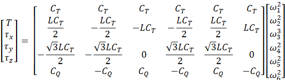 (6)
(6)
Newton’s equations of linear motion in the world frame can then be defined as:
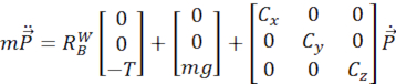 (7)
(7)
Rotation matrix  is defined by Z-X-Y Euler Angle rotation:
 (8)
(8)
where the yaw angle ( ) is rotation about the Z-axis, the roll angle (
 ) is rotation about the X-axis, the pitch angle (
 ) is rotation about the Y-axis, and the shorthand notation
  , is for each angle.
In these experiments, we are only concerned with aerodynamic forces acting on the hexacopter in linear motion, but for completeness in understanding the dynamics of the hexacopter, the attitude equations of motion are defined below. First, p is defined as angular velocity about the body’s X-axis, q is the angular velocity about the body’s Y-axis, and r is the angular velocity about the body’s Z-axis.
 (9)
(9)
 is the upward force applied by thruster i, and I is the hexacopter moment of inertia matrix that can be determined using a bifilar pendulum. Further information for this procedure can be obtained from Quan8. Body and world frame angular velocities are related by:
 (10)
(10)
Процедура
This protocol characterizes hexacopter thrust and aerodynamics. For this experiment, we used commercially available, off-the-shelf components for the hexacopter, and the details are provided in Table 2. For the flight controller, we selected an open-source autopilot, Librepilot,9 as it provided flexibility to control individual motor commands issued to the hexacopter.
The test stand for mounting the load cell and hexacopter was fabricated in-house using laminated plywood and is shown in Figure 2. When designing the test stand, note that it must allow accurate adjustment of the multicopter’s angle of attack and be sufficiently rigid to withstand bending forces and vibrations created while operating the motors.
A 6-axis load cell is mounted on the test stand and connected to the data acquisition board, as shown in Figure 3. Aerodynamic and thrust forces are sensed in the body frame of the hexacopter by the load cell. Strain gauge data passes through a signal conditioner. The data acquisition (DAQ) board then acquires the analog force and torque components using a calibration procedure provided by the load cell manufacturer. The DAQ board then stores these values in a high-speed buffer and later to permanent disk.
For this protocol, first, determine the forces generated by the individual motors. Then determine the forces acting on the bare airframe, followed by determining the forces generated by the whole hexacopter as a function of motor RPM commands. Issue the same RPM commands to all motors for each test.
1. Dynamometer Experiment
The dynamometer allows direct measurement of parameters, including thrust, torque, RPM, battery voltage, and current. Parameters such as electrical power, mechanical power, and motor efficiency can then be derived from Equations (3), (4), and (5).
- Connect the dynamometer to the DAQ computer using a USB connector.
- Run the graphical user interface (GUI) provided with the dynamometer.
- Calibrate the dynamometer by following the on-screen instructions provided. Use weights and a known lever arm when prompted.
- Mount the motor on the dynamometer test stand.
- Attach the propeller in a puller (tractor) configuration, as shown in Figure 4.
- Connect the battery to the dynamometer.
- Firmly secure the dynamometer to the workbench using C-clamps.
- Run the step input program and record the measured parameters, including thrust, torque, motor RPM, motor current, and pulse width modulation (PWM) “throttle” command.
2. Static Thrust Test
- Fasten the hexacopter on the load cell test stand using mounting screws.
- Open the Data Acquisition System (DAQ), and run the load cell strain gauge bias program.
- Connect the hexacopter flight controller to the computer using a micro USB cable and open the Ground Controller Station (GCS) software.
- Connect the power supply to the hexacopter.
- Select the Configuration tab -> Output in GCS. Link all the motors, and check the Live testing of the outputs.
- Set the desired throttle command to 1300 ms. Make sure you can operate all motors with the same throttle (PWM) command.
- Let the system stabilize for several seconds, and then run the DAQ program to collect data from the load cell.
- After data collection is complete, stop the motors.
- Repeat steps 3. 6 to 3.8 for throttle commands 1500 ms and 1700 ms.
- Transfer data stored in the DAQ system to a data processing computer and long-term storage.
3. Dynamic Thrust Test
Conduct a series of wind tunnel tests to characterize and analyze the hexacopter’s linear aerodynamic forces, primarily lift and drag, over a variety of airspeeds and incidence angles. During the wind tunnel experiments, the hexacopter is assumed to be in steady flight conditions. Therefore, the magnitude of the hexacopter velocity vector is the same as airspeed and assumed horizontal in the world frame. Lift and drag forces are primarily due to the flow of air around the hexacopter. Note that lift and drag forces are assumed to characterize the total lift and total drag on hexacopter; side forces are negligible.
The experimental procedure performed in this experiment is similar to those reported in Foster10 and Russell11. During wind tunnel testing, the hexacopter was driven by a power converter plugged into building (AC) power to assure consistent power and voltage levels throughout all tests. Note that motors at high RPMs can consume appreciable current; use low gauge and short length wire to prevent appreciable voltage drop across the wire during operation.
- Mount the hexacopter on the load cell test stand
- Connect the load cell to the DAQ computer, and connect the hexacopter to the GCS using the procedure described for the Static Thrust Test.
- Secure the test stand to the base of the wind tunnel with C-clamps.
- Make sure the multicopter is well clear of wind tunnel walls, floor, and ceiling to minimize free stream flow disturbance and reflection.
- Mount pitot tubes several feet away from the hexacopter to sample undisturbed airflow. Connect the pitot pressure sensors to the DAQ system.
- Set the pitch angle for the hexacopter to 0° by adjusting the hinge joint of the test stand. In the wind tunnel, hexacopter pitch angle and angle of attack are identical.
- Run the bias program to establish load cell voltage biases.
- Initialize the wind tunnel to the wind speed of 2.2 m/s.
- Once the free stream flow speed settles to the desired value, collect baseline FT readings from the load cell with hexacopter motors off.
- Initialize the throttle command to 1300 ms, let the airspeed in the wind tunnel settle before collecting FT and pitot data.
- Repeat steps 3.7 - 3.9 for throttle commands of 1500 ms and 1700 ms.
- Repeat Steps 3.5 - 3.10 for different hexacopter pitch angles and wind tunnel airspeed values, as stated in Table 1.
Результаты
Dynamometer Tests
In Figures 5-6, the plots illustrate the variation of thrust and torque, respectively, with increasing motor RPM. From these plots, the minimum motor RPM required for the multicopter to hover can be determined. A plot showing data from multiple propellers can be obtained from Sharma12. Further, the quadratic relations between thrust vs. RPM and moment vs. RPM can be clearly observed, which are described in Equations (1) and (2). Using this quadratic relationship, we can then determine the and  coefficients for the 6040 propeller, which are as follows:

Figure 7 shows that an increase in RPM corresponding with an increase in electrical power consumption results in decreased motor efficiency. Similar experiments can be conducted for different propellers to obtain motor efficiency for the motor-propeller pair. The results from such experiments are useful during vehicle design to determine the optimal motor-propeller pair to be used on the multicopter. These decisions are based on the desired mission parameters, such as the duration and speed of the flight.
Since there is no direct RPM sensor feedback on the low-cost hexacopter, we estimate RPM by fitting a surface across RPM, electrical power, and throttle (PWM) command. This surface fit is used to estimate RPM as a function of electrical power and PWM value. Based on data collected from the dynamometer, the surface fit is shown in Figure 8, with the corresponding equation:


where  is the motor PWM (throttle) setting normalized by the mean bias value 1550
  with a standard deviation of 201.9
  , while is normalized by bias 71.11 W with a standard deviation of 55.75 W.
After analyzing the dynamometer data, a second dataset was collected for validation and provided as an input to  function. The results are then plotted in a time series of RPM variation, as seen in Figure 9 and Figure 10. These plots confirm that the fit estimates RPM to within 95% bounds of the actual RPM, as shown in Figure 9.
Wind Tunnel Results
Experiments in the wind tunnel were conducted following the test matrix in Table 1. To reduce complexity, a zero yaw (sideslip) angle condition was maintained at all times. This is consistent with most flight profiles in which cameras and other sensors are mounted with a preferred forward-facing orientation. The variation of drag and lift are plotted against different pitch angles of the hexacopter and are shown in Figures 11 and 12, respectively. Both plots show that increasing the throttle command results in a significant increase in lift (motor thrust) force. Similarly, an increase in wind tunnel speed results in a significant increase in the drag force acting on hexacopter. These trends are consistent with Equation (7).
A static thrust model only requires dynamometer testing. However, to gain an accurate estimate of dynamic thrust and drag, wind tunnel experiments with FT load cell sensing were required. With collected data, we can develop a lookup table of and and drag coefficients , as a function of pitch angle and free stream airspeed to enable accurate hexacopter FT modeling.

Figure 1. Reference world and body coordinate frames. Please click here to view a larger version of this figure.

Figure 2. Multicopter load cell test stand. Please click here to view a larger version of this figure.

Figure 3. Wind tunnel data acquisition (DAQ) system diagram. Please click here to view a larger version of this figure.

Figure 4. Dynamometer setup. Please click here to view a larger version of this figure.

Figure 5. Relationship between motor thrust and RPM. Please click here to view a larger version of this figure.

Figure 6. Relationship between motor torque and RPM. Please click here to view a larger version of this figure.
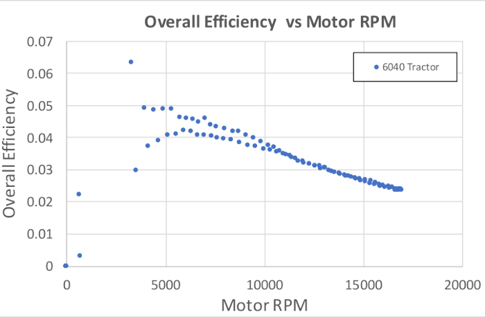
Figure 7. Overall motor efficiency vs. RPM. Please click here to view a larger version of this figure.

Figure 8. Surface fit over throttle (PWM), electrical power, and RPM. Please click here to view a larger version of this figure.
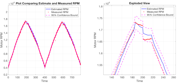
Figure 9. Validation of  with RPM measured directly from the dynamometer. Please click here to view a larger version of this figure.
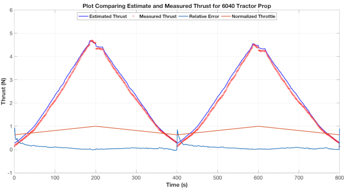
Figure 10. Validation of estimated thrust data with measured thrust data. Please click here to view a larger version of this figure.

Figure 11. Load cell lift and drag forces for different pitch angles and throttle commands given constant wind speed of 5 m/s. Please click here to view a larger version of this figure.

Figure 12. Load cell lift and drag forces for different pitch angles and throttle commands given constant wind speed of 8.47 m/s. Please click here to view a larger version of this figure.
Table 1. Wind tunnel test matrix
| Wind Tunnel Test Matrix | |||
| Wind Speed (m/s) | Pitch Angle (°) | Yaw Angle(°) | Throttle Command (ms) |
| 2.2 | 30 to -30 | 0 | 0 and 1300 to 1700 |
| 4.5 | 30 to -30 | 0 | 0 and 1300 to 1700 |
| 6.7 | 30 to -30 | 0 | 0 and 1300 to 1700 |
| 8.9 | 30 to -30 | 0 | 0 and 1300 to 1700 |
Table 2. Parts list
| Parts List for Hexacopter | |||||
| Sr No | Part No | Description | Img | Link | Qty |
| 1 | SKU: 571000027-0 | HobbyKing™ Totem Q450 Hexacopter Kit | 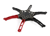 |
https://hobbyking.com/en_us/hobbykingtm-totem-q450-hexacopter-kit.html | 1 |
| 2 | SKU: 571000064-0 | OpenPilot CC3D Revolution (Revo) 32bit F4 Based Flight Controller w/Integrated 433Mhz OPLink |  |
https://hobbyking.com/en_us/openpilot-cc3d-revolution-revo-32bit-flight-controller-w-integrated-433mhz-oplink.html | 1 |
| 3 | SKU: 571000065-0 | Openpilot OPLink Mini Ground Station 433 MHz |  |
https://hobbyking.com/en_us/openpilot-oplink-mini-ground-station-433-mhz.html | 1 |
| 4 | SKU: 9536000003-0 | Multistar Elite 2204-2300KV 3-4s 4 pack (2/CCW 2/CW) |  |
https://hobbyking.com/en_us/multistar-elite-2204-2300kv-set-of-4-cw-ccw-2-ccw-2-cw.html | 2 |
| 5 | SKU: 9192000131-0 | Afro 20A Muti-Rotor ESC (SimonK Firmware) |  |
https://hobbyking.com/en_us/afro-esc-20amp-multi-rotor-motor-speed-controller-simonk-firmware.html | 8 |
| 6 | SKU: T2200.3S.30 | Turnigy 2200mAh 3S 30C Lipo Pack |  |
https://hobbyking.com/en_us/turnigy-2200mah-3s-30c-lipo-pack.html | 1 |
| 7 | SKU: 9171000144 | Hobby King Octocopter Power Distribution Board | 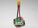 |
https://hobbyking.com/en_us/hobby-king-octocopter-power-distribution-board.html | 1 |
| 8 | SKU: 426000022-0 | King KongMultirotor Prop 6x4 CW/CCW | 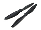 |
https://hobbyking.com/en_us/kingkong-multirotor-propeller-6x4-cw-ccw-black-20pcs.html | 1 |
| 8 | SKU: 329000304-0 | Gemfan Propeller 5x3 Black (CW/CCW) (2pcs) | 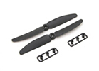 |
https://hobbyking.com/en_us/gemfan-propeller-5x3-black-cw-ccw-2pcs.html | 10 |
| 9 | - | Spektrum DX6 Transmitter System MD2 with AR610 Receiver | 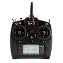 |
https://www.amazon.com/Spektrum-Transmitter-System-AR610-Receiver/dp/B01B9DYOWG/ref=sr_1_2?ie=UTF8&qid=1494000219&sr=8-2&keywords=spektrum+dx6 | 1 |
| 10 | 709-RSP-1600-12 | Switching Power Supplies 1500W 12V 125A |  |
https://www.mouser.com/ProductDetail/Mean-Well/RSP-1600-12/?qs=%2fha2pyFadujYDPrAgY3T1JlGoR5AZMKL7jhmRydJUc1Z44%252bNekUvbQ%3d%3d | 1 |
| Parts List for DAQ | |||||
| Sr No | Part No | Description | Img | Link | Qty |
| 1 | ATHM800-256ALP Rev F | Athena II PC /104 SBC |  |
http://www.diamondsystems.com/products/athenaii | 1 |
| 2 | SI-145-5 | Mini 45 Force /Torque Sensor |  |
http://www.ati-ia.com/products/ft/ft_models.aspx?id=Mini45 | 1 |
| 3 | - | Hobbypower Airspeed Sensor MPXV7002DP Differential Pressure |  |
https://www.amazon.com/Hobbypower-Airspeed-MPXV7002DP-Differential-controller/dp/B00WSFWO36/ref=pd_day0_21_2?_encoding=UTF8&pd_rd_i=B00WSFWO36&pd_rd_r=8KRZ03PR2XAJ1HXD4BKS&pd_rd_w=M1tek&pd_rd_wg=LVHjU&psc=1&refRID=8KRZ03PR2XAJ1HXD4BKS | 1 |
| Parts List for Dynamometer | |||||
| Sr No | Part No | Description | Img | Link | Qty |
| 1 | Series-1580 | RC Benchmark Dynamometer |  |
https://www.rcbenchmark.com/dynamometer-series-1580/ | 1 |
Заявка и Краткое содержание
Here we describe a protocol to characterize the aerodynamic forces acting on a hexacopter. This protocol can be applied to other multirotor configurations directly. Proper characterization of aerodynamic forces is needed to improve control design, understand flight envelope limits, and estimate local wind fields as in Xiang13. The presented protocol for determining motor RPM based on power consumption and throttle command has direct applications to estimate RPM and thrust when low-cost electronic speed controllers (ESCs) without RPM sensing are used. Finally, the application of advanced control techniques, such as in model predictive control for trajectory tracking, require knowledge of vehicle aerodynamics and thrust forces, as described in Kamel14.
Ссылки
- Clothier, R.A., and Walker, R.A., “Safety Risk Management of Unmanned Aircraft Systems,” Handbook of Unmanned Aerial Vehicles, Springer, 2015, pp. 2229–2275.
- Ampatis, C., and Papadopoulos, E., “Parametric Design and Optimization of Multi-rotor Aerial Vehicles,” Applications of Mathematics and Informatics in Science and Engineering, Springer, 2014, pp. 1–25.
- Bershadsky, D., Haviland, S., and Johnson, E. N., “Electric Multirotor UAV Propulsion System Sizing for Performance Prediction and Design Optimization,” 57th AIAA/ASCE/AHS/ASC Structures, Structural Dynamics, and Materials Conf., 2016.
- Bangura, M., Melega, M., Naldi, R., and Mahony, R., “Aerodynamics of Rotor Blades for Quadrotors,” arXiv preprint arXiv:1601.00733, 2016
- Ducard, G., and Minh-Duc Hua. "Discussion and Practical Aspects on Control Allocation for a Multi-rotor Helicopter." Conf. on Unmanned Aerial Vehicle in Geomatics, 2011.
- Powers C., Mellinger D., Kumar V. “Quadrotor Kinematics and Dynamics” In: Handbook of Unmanned Aerial Vehicles. Springer, 2015
- McClamroch, N. Harris. “Steady Aircraft Flight and Performance.” Princeton University Press, 2011.
- Quan, Q., “Introduction to Multicopter Design and Control”, Springer Singapore, 2017.
- LibrePilot, https://www.librepilot.org/site/index.html
- Foster, J. and Hartman, D., “High-Fidelity Multi-Rotor Unmanned Aircraft System Simulation Development for Trajectory Prediction under Off-Nominal Flight Dynamics,” Proc. Air Transportation Integration & Operations (ATIO) Conference, AIAA, 2017.
- Russell, Carl R., et al. "Wind Tunnel and Hover Performance Test Results for Multicopter UAS Vehicles," 2016.
- Sharma, P. and Atkins, E., “An Experimental Investigation of Tractor and Pusher Hexacopter Performance,” Proc. AIAA Aviation Conference, AIAA, June 2018. (to appear)
- Xiang, X., et al. "Wind Field Estimation through Autonomous Quadcopter Avionics." 35th AIAA/IEEE Digital Avionics Systems Conference (DASC), IEEE, 2016.
- Kamel, M., et al. "Model Predictive Control for Trajectory Tracking of Unmanned Aerial Vehicles using Robot Operating System." Robot Operating System (ROS). Springer, Cham, 2017, 3-39.
Перейти к...
Видео из этой коллекции:

Now Playing
Multicopter Aerodynamics: Characterizing Thrust on a Hexacopter
Aeronautical Engineering
9.1K Просмотры

Aerodynamic Performance of a Model Aircraft: The DC-6B
Aeronautical Engineering
8.3K Просмотры

Propeller Characterization: Variations in Pitch, Diameter, and Blade Number on Performance
Aeronautical Engineering
26.1K Просмотры

Airfoil Behavior: Pressure Distribution over a Clark Y-14 Wing
Aeronautical Engineering
21.0K Просмотры

Clark Y-14 Wing Performance: Deployment of High-lift Devices (Flaps and Slats)
Aeronautical Engineering
13.3K Просмотры

Turbulence Sphere Method: Evaluating Wind Tunnel Flow Quality
Aeronautical Engineering
8.7K Просмотры

Cross Cylindrical Flow: Measuring Pressure Distribution and Estimating Drag Coefficients
Aeronautical Engineering
16.1K Просмотры

Nozzle Analysis: Variations in Mach Number and Pressure Along a Converging and a Converging-diverging Nozzle
Aeronautical Engineering
37.8K Просмотры

Schlieren Imaging: A Technique to Visualize Supersonic Flow Features
Aeronautical Engineering
11.4K Просмотры

Flow Visualization in a Water Tunnel: Observing the Leading-edge Vortex Over a Delta Wing
Aeronautical Engineering
8.0K Просмотры

Surface Dye Flow Visualization: A Qualitative Method to Observe Streakline Patterns in Supersonic Flow
Aeronautical Engineering
4.9K Просмотры

Pitot-static Tube: A Device to Measure Air Flow Speed
Aeronautical Engineering
48.7K Просмотры

Constant Temperature Anemometry: A Tool to Study Turbulent Boundary Layer Flow
Aeronautical Engineering
7.2K Просмотры

Pressure Transducer: Calibration Using a Pitot-static Tube
Aeronautical Engineering
8.5K Просмотры

Real-time Flight Control: Embedded Sensor Calibration and Data Acquisition
Aeronautical Engineering
10.1K Просмотры
Авторские права © 2025 MyJoVE Corporation. Все права защищены