Electroplating of Thin Films
Overview
Source: Logan G. Kiefer, Andrew R. Falkowski, and Taylor D. Sparks, Department of Materials Science and Engineering, The University of Utah, Salt Lake City, UT
Electroplating is a process that uses electric current to reduce dissolved metal cations so that they form a thin coating on an electrode. Other thin film deposition techniques include chemical vapor deposition (CVD), spin coating, dip coating, and sputter deposition among others. CVD uses a gas-phase precursor of the element to be deposited. Spin coating spreads the liquid precursor centrifugally. Dip coating is similar to spin coating, but rather than spinning the liquid precursor, the substrate is completely submerged in it. Sputtering uses plasma to remove the desired material from a target, which then plates the substrate. Techniques such as CVD or sputtering produce very high quality films but do so very slowly and at high cost since these techniques typically require a vacuum atmosphere and small sample size. Electrodeposition doesn't rely on a vacuum atmosphere which greatly reduces the cost and increases scalability. In addition, relatively high rates of deposition can be achieved with electrodeposition.
Principles
Galvanic cells consist of two different metals connected by a salt bridge or porous membrane. These electrochemical cells have oxidation and reduction half-cell reactions which spontaneously occur to derive energy. Electrodeposition reverses the galvanic cell by supplying energy to drive non-spontaneous redox reactions to plate an electrode with a thin film. The anode is made of the metal to be plated and is oxidized by supplying direct current. This oxidation at the anode creates ions which dissolve and flow through the electrolytic solution, which contains metal salts and other ions to permit the flow of electricity. The dissolved ions are reduced and plated onto the cathode. Electrochromic cells change their optical absorption when subjected to a voltage. As with electroplating, driving electrochromic redox reactions allows these materials to transition between bleached and colored states, as with the coated material Prussian Blue.
The process of electroplating requires both materials used in the process to be conductive, as such metals and metallic compounds are primarily used. In order for the plating to be successful, the surface of the material that will be plated needs to be completely clean. Surface cleanliness is ensured by dipping the material in a strong acid or briefly connecting the electroplating circuit in reverse - if the electrode is clean, atoms from the plating metal will bond to it effectively. Even if the surface is clean, ineffective plating can result when components have complex geometries, which lead to an uneven distribution of plating thickness. Plating thickness can be controlled by varying the duration of electric current between the metals and the strength of the current applied between metals. Increasing either or both of these will increase the thickness of the plating. By controlling the thickness of the plating, plating issues resulting from complex geometries can be avoided.
The goal of the proposed technique is to electroplate a thin film of Prussian Blue onto a sheet of ITO coated PET, and then measure the film's ability to absorb and transmit light using UV-Vis Spectroscopy. The UV-Vis data of the electrochromic thin film in the bleached and colored state will quantify the color differences between the film in these two states. Also, thicker electrochromic films will achieve a more profound colored state, and therefore absorb relatively more light when compared to thinner films. Therefore, UV-Vis can also be used to make qualitative thickness comparisons between films.
Procedure
- Prepare Prussian Blue solution by mixing 50 mL of 0.05 M hydrochloric acid (HCl), 100 mL of 0.05 M potassium ferricyanide (K3[Fe(CN)6]), and 100 mL of 0.05 M iron(III) chloride hexahydrate (FeCl3.6H2O).
- Create anode by wrapping approximately 8 cm of nichrome wire (NiCr) into a tight coil.
- Prepare the cathode substrate by removing the outer coating that protects the conductive side of a 5X5 centimeter sheet of ITO coated PET.
- Build circuit by connecting the positive terminal of a 9 volt (9V) battery in series to a 30 ohm resistor, and then to the NiCr anode using an alligator clip. Connect the negative end of the battery to the ITO cathode substrate using an alligator clip. Ensure that the cathode and the anode are not touching in the solution.
- After preparing the circuit and the Prussian Blue solution, lower the cathode and anode into the solution, taking care not to submerge either alligator clip. Hold for 2 minutes, then remove and rinse both the cathode and anode in DI water. This step can be repeated with varied submersion times to vary the thickness of the coating.
- Analyze the sample using the Perkin Elmer Lambda 950 UV-Vis spectrometer, determining its transmittance of visible light ranging in wavelength from 750-400 nm. Be sure to analyze the background level of transmittance by scanning an ITO coated PET sample that has not been coated with Prussian Blue.
- After running the Prussian Blue sample in the UV-Vis, prepare a 150 mL solution of 1.0 M potassium chloride (KCl).
- Use the same circuit and NiCr anode (using the 9V battery in series), and an additional alligator clip to connect both sides of the Prussian Blue layer to the circuit. Submerge the anode and cathode in the KCl solution for 1.5 minutes, driving the electrochromic transition from colored to bleached.
- Then remove and rinse both the cathode and anode in DI water as before.
- Run the bleached sample in the UV-Vis, using the aforementioned transmittance scat parameters.
Results
Qualitatively, the ITO coated in Prussian Blue, will become transparent when a negative potential is applied as shown in Figure 1 below. This change can be reversed by applying a positive voltage.
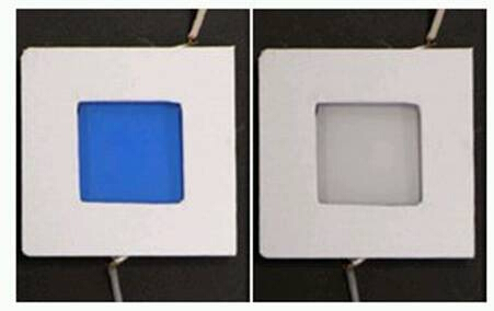
Figure 1: Prussian Blue in its colored and bleached states.
More qualitatively, the thickness of the deposited layer can be changed and measured in various ways including by changing the electrodeposition voltage or the electrodeposition time. For Prussian Blue, varying layer thicknesses will affect the percent transmittance of light through the sample. The relationship between the amount of Prussian Blue deposited on the ITO and the degree of opacity can be measured through UV-Visible spectrophotometry and is shown in Figures 2 and 3.
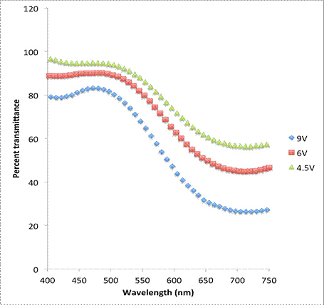
Figure 2: UV-Vis spectroscopy of Prussian Blue in its colored state for various electrochemical deposition voltages.

Figure 3: UV-Vis spectroscopy of Prussian Blue in its colored state for various electrochemical deposition times.
Films deposited at a higher voltage saw a lower percent transmittance than those deposited at a lower voltage. This indicates that the layers are thicker at higher voltages than at lower voltages. Additionally, samples electrodeposited for longer times saw lower percent transmittances, again indicating that the films are thicker at longer deposition times.
Application and Summary
Electrodeposition, as demonstrated in this experiment, allows for the modification of a materials surface properties within minimal change in volume. In the process of electrodeposition, an electric current is passed through an electrolytic solution between an anode and a cathode. The positively charged cations in the electrolyte solution are attracted to and deposited onto the negatively charged cathode. Once deposited, the atoms in the layer gain electrons through the process of reduction.
The speed and amount of electrodeposition depends on the strength of the electric current applied between the cathode and anode in the electrolyte solution. Additionally, the metals used in electrodeposition must be chosen carefully, as some metals will alloy with one another; in those cases, multiple metal layers must be deposited.
Because the cations are chemically bonded the substrate, electrodeposition has the advantages of unified thermal expansion, better resistance to chemical corrosion, and increased physical durability. One drawback of electrochemical deposition compared other methods of thin film deposition is the necessity of a conductive surface on the substrate prior to deposition. Additionally, the process of electrodeposition does not always yield uniform deposition, which causes inconsistencies in the coating of the material.
Electrodeposition has many applications beyond depositing Prussian Blue. Electrodeposition is used extensively in the jewelry industry as it allows for a high degree of control over the plating process and allows for varied aesthetic modifications. A wide variety of color variations can be achieved by depositing different metals to form alloys with unique appearances. Additionally, metals can be deposited in a uniform fashion, which reduces color inconsistencies and can hide solder and component lines. By utilizing electrodeposition, jewelers are able to create functional and consistent metal coatings that are aesthetically pleasing.
Electrodeposition is also used in the automotive industry. Vehicles are constantly subject to forces that wear to vital components. Electrodeposition allows for the properties of various parts to be modified and enhanced without changing functional volume of the part. Deposited chromium provides superior wear and corrosion protection for vehicles and allows cars to last longer with minimum requirements for maintenance and repair.
In the semiconductor industry, electrodeposition offers significant cost, reliability and environmental advantages over classical evaporation technology and can accommodate vastly different wafer sizes. The electrodeposition process allows for deposition on fragile substrates and also permits advanced shape control or new functionalities. Electrodeposition offers a means of inexpensively unique samples by utilizing a technology readily adapted to industrial production.
Tags
Skip to...
Videos from this collection:

Now Playing
Electroplating of Thin Films
Materials Engineering
19.6K Views

Optical Materialography Part 1: Sample Preparation
Materials Engineering
15.3K Views

Optical Materialography Part 2: Image Analysis
Materials Engineering
10.9K Views

X-ray Photoelectron Spectroscopy
Materials Engineering
21.5K Views

X-ray Diffraction
Materials Engineering
88.2K Views

Focused Ion Beams
Materials Engineering
8.8K Views

Directional Solidification and Phase Stabilization
Materials Engineering
6.5K Views

Differential Scanning Calorimetry
Materials Engineering
37.1K Views

Thermal Diffusivity and the Laser Flash Method
Materials Engineering
13.2K Views

Analysis of Thermal Expansion via Dilatometry
Materials Engineering
15.6K Views

Electrochemical Impedance Spectroscopy
Materials Engineering
23.0K Views

Ceramic-matrix Composite Materials and Their Bending Properties
Materials Engineering
8.0K Views

Nanocrystalline Alloys and Nano-grain Size Stability
Materials Engineering
5.1K Views

Hydrogel Synthesis
Materials Engineering
23.5K Views
Copyright © 2025 MyJoVE Corporation. All rights reserved