
Inductance
Overview
Source: Yong P. Chen, PhD, Department of Physics & Astronomy, College of Science, Purdue University, West Lafayette, IN
This experiment will use inductive coils to demonstrate the concept of inductor and inductance. Magnetic induction will be demonstrated using a rod magnet inserted into or extracted away from the core of a coil to induce a transient electromotive force (emf) voltage in the coil, measured by a voltmeter. This experiment will also demonstrate the mutual inductance between two coils, where turning on or off a current flowing in a coil can induce an emf voltage in a second coil nearby. Finally, the experiment will demonstrate the self-inductance of a coil, when switching a current off induces an emf to light up a light bulb connected in parallel with the coil.
Principles
According to the Faraday's law, a changing (time-dependent) magnetic field B will induce an electric field, known as the electromotive force (emf) field. If the magnetic field is transverse to a single-loop coil, the emf field will generate an emf voltage V across the two ends of the coil:
 (Equation 1)
The magnetic flux through the loop is,

where A is the area of the loop, and if the magnetic field B is along a general direction, B must be replaced with its component perpendicular to the area of the loop, and ΔΦ/Δt is the rate of its change. The minus sign in Equation 1 signifies the direction of the induced emf (or voltage): it always tries to oppose the change of the external B field by generating a current in the coil that produces its own magnetic field in the opposite direction of the change of the B field. The direction of the induced magnetic field is related to the direction of the current in the coil by the red hand rule (wrap the fingers of the right hand around the current direction, the thumb points in the direction of the magnetic field produced by the current). For example, if the external B field is along the +x direction (the area of the loop is in yz plane) and is increasing with time, then the magnetic field generated by the induced emf and current will be in the -x direction; if the external B field is decreasing, the induced emf and current will generate a magnetic field in the +x direction. This is the phenomenon of magnetic induction. For a "solenoid" coil of N turns, the emf voltage generated by each turn will add up to a total emf voltage. During the magnetic induction, the coil can be thought of as an analogue of a battery that would output a voltage and (if some load is connected) a current. In this experiment, this phenomenon will be demonstrated using an increasing or decreasing magnetic field B produced by: (1) a permanent magnet moved toward or away from the coil (Figure 1); (2) another coil with a current I flowing through the coil, where I can be switched on or off (Figure 2); and (3) the coil itself with a current I flowing through, where I can be switched on or off (Figure 3). In the case of (3), the induction is referred as self-induction (and the solenoid is an example of an "inductor"). For both cases (2) and (3), since the magnetic flux or magnetic field (whose change causes the induction) is proportional to the current I, the induced emf voltage is proportional to the rate of the change of the current (ΔI/Δt), with the proportional factor L known as the mutual inductance as in case (2) or self-inductance as in case (3), respectively:
 (Equation 2)
The direction of the voltage V is determined in a similar manner as described above: the emf V will try to produce a current I, and its own magnetic field that opposes the change in the original magnetic field B.
Procedure
1. Magnetic Induction
- Obtain a solenoid coil (with a hollow core) and a rod magnet (with its North and South poles labeled).
- Obtain an analogue bipolar ammeter with an indicator needle. The needle is nominally at the middle position at zero reading, and will deflect to the right or left depending on the direction of current flow (positive reading means the current flows from the positive terminal to and negative terminal inside the ammeter).
- Connect the two ends of the solenoid to the "+" and "−" terminals of the ammeter, as in Figure 1. The connection can be made with cables with clamps or banana plugs into receiving ports on the instruments.
- Bring the rod magnet closer to the coil and insert its north end into its core, as shown in Figure 1. Observe the ammeter and record the sign of its reading. For all observations to be conducted in the following, always record both the sign and the approximate magnitude of the reading.
- Extract the magnet back out of the coil, and observe the reading on the ammeter.
- With the rod magnet far away from the coil, flip it over and now move the South end closer to the coil. Insert the South end into the core of the coil, and observe the reading on the ammeter.
- Extract the magnet back out of the coil again, and observe the reading on the ammeter.
- Repeat steps 1.6 and 1.7 above again (insert and extract South pole of the magnet) but with a slower and then a faster speed, and observe and compare the reading on the ammeter.

Figure 1: Diagram showing a magnet moving toward/away from a coil to induce a current in the coil (magnetic induction).
2. Mutual Inductance
- Obtain a second solenoid coil (referred to as coil #2), and bring it close to the first coil (referred as coil #1) as shown in Figure 2. The two coils are aligned approximately along a common axis.
- Connect the two ends of coil #2 to a DC voltage source with a switch, as shown in Figure 2. Coil #1 is still connected to the analogue ammeter.
- With the switch open, set the voltage source to +2 V, then close the switch to allow a current to flow in the coil #2, and observe the reading on the ammeter connected to coil #1 when the switch is turned on.
- Now open the switch, and observe the reading on the ammeter.
- Set the voltage source to −2 V (or alternatively, swap the two wires connected to the plus and minus terminals of the voltage source to reverse the sign of the voltage and current to be applied to coil #1), repeat steps 2.3 (switch on) and 2.4 (switch off), and observe the ammeter connected to coil #1.
- Now insert coil #2 into the core of coil #1 as fully as possible, repeat the above step 2.5, and observe the reading on the ammeter connected to coil #1.

Figure 2: Diagram showing that a current switching on or off in a coil would induce current in another nearby coil (mutual induction).
3. Self-inductance
- Obtain a light bulb and connect it in series with the ammeter, then connect the combination to coil #2 in parallel with the volt supply, as shown in Figure 3. The voltage on the volt supply is set to be 1 V.
- Close the switch to let the current flow through the coil. The light bulb should be dim because the coil has a much smaller resistance than the light bulb, and most of the current will flow through the coil.
- Open the switch so that the volt supply is disconnected from the rest of the circuit, and observe the light bulb and the ammeter reading when the switch is just opened.
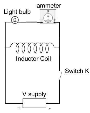
Figure 3: Diagram showing a circuit to demonstrate self-induction, where tuning off current in a coil induces a transient voltage and current in a light bulb connected to it.
Results
Representative results for what may be observed on the ammeter reading for Sections 1 and 2 (setups in Figures 1 and 2) are summarized in Tables 1 and 2 below.
| Procedure Step | Orientation of Rod Magnet | Motion of Magnet | Reading on the ammeter |
| 1.4 | South-North (North is at the right end of rod, as in Figure 1) | Moving toward coil (left end) | Positive |
| 1.5 | South-North | Moving away from the coil | Negative |
| 1.6 | North-South | Moving toward coil | Negative |
| 1.7 | North-South | Moving away from the coil | Positive |
Table 1: Representative results for Section 1. For step 1.8, observe that a faster speed of motion gives a larger reading (larger needle deflection) on the ammeter.
| Procedure Step | Volt Supply Setting | Switch action | Reading on the ammeter |
| 2.3 | +2 V | Turning on | Positive |
| 2.4 | +2 V | Turning off | Negative |
| 2.5 | −2 V | Turning on | Negative |
| 2.5 | −2 V | Turning off | Positive |
Table 2: Representative results for Section 2. For step 2.6, observe that placing coil #2 inside coil #1 gives a larger reading (while the signs of the reading remain the same) on the ammeter compared to step 2.5 for each corresponding switch action.
For Section 3, if initially the current due to the volt supply (+1 V) is flowing from the right to the left in the coil, turning it off (opening the switch) will induce a transient current along the same direction. The light bulb will light up briefly, and the ammeter will register a positive reading for the connection given in Figure 3.
Application and Summary
In this experiment, we have demonstrated how changing a magnetic field (by moving a magnet) induces a current in a coil, and also how changing the current in the coil induces current in another coil (mutual induction). We also demonstrated that changing the current in a coil induces a voltage and current in the same coil (self-induction).
Inductors (typically in the form of coils) are commonly used in many circuit applications, such as to store magnetic energy when a steady state current flows. They are useful for electrical signal processing; for example, taking the derivative or integral of an electrical signal, for filtering, and for resonance circuits. They are also used in transformers to change the voltage of AC signals.
The author of the experiment acknowledges the assistance of Gary Hudson for material preparation and Chuanhsun Li for demonstrating the steps in the video.
Skip to...
Videos from this collection:

Now Playing
Inductance
Physics II
21.7K Views

Electric Fields
Physics II
77.7K Views

Electric Potential
Physics II
105.4K Views

Magnetic Fields
Physics II
33.7K Views

Electric Charge in a Magnetic Field
Physics II
33.7K Views

Investigation Ohm's Law for Ohmic and Nonohmic Conductors
Physics II
26.3K Views

Series and Parallel Resistors
Physics II
33.2K Views

Capacitance
Physics II
43.9K Views

RC/RL/LC Circuits
Physics II
143.2K Views

Semiconductors
Physics II
30.0K Views

Photoelectric Effect
Physics II
32.8K Views

Reflection and Refraction
Physics II
36.4K Views

Interference and Diffraction
Physics II
91.5K Views

Standing Waves
Physics II
50.0K Views

Sound Waves and Doppler Shift
Physics II
23.5K Views
Copyright © 2025 MyJoVE Corporation. All rights reserved