
Capacitance
Genel Bakış
Source: Yong P. Chen, PhD, Department of Physics & Astronomy, College of Science, Purdue University, West Lafayette, IN
This experiment will use commercial capacitors and a parallel plate capacitor to demonstrate the concept of capacitance. A capacitor stores opposite charges on two conductors, for example two opposite metal plates, leading to a potential difference (voltage drop) between the two conductors. The amount of charge on each conductor is proportional to this voltage drop, with the capacitance as the proportionality factor. If the voltage is changing with time, the current flowing into the capacitor will be proportional to the rate of that change, and again the capacitance is the proportionality factor.
The capacitance of the parallel plate capacitor is the product of the dielectric constant with the distance between the plates divided by the area of the plate. This experiment will demonstrate the proportionality with distance by first depositing some charge onto the capacitor and then using a high-impedance voltmeter (electrometer) to monitor the voltage between the plates as the distance is increased. The voltage change will also be monitored with a dielectric material, such as a plastic plate inserted into the space between the metal plates.
A capacitance meter will be used to directly measure the capacitance, as well as to measure parallel and series connections of commercially-available capacitors and to study how the total capacitance is related to individual capacitances.
İlkeler
A capacitor consists of two separated conductors and its capacitance C represents its "capacity to store charge". Applying a voltage difference V between these two conductors can induce charge +Q on one conductor and Q on the other conductor (so the total charge is zero, that is, the capacitor as a whole is charge neutral), such that:
 (Equation 1)
Note here that Q is the charge on one conductor (not the total charge on both conductors which would be 0). If the voltage V is changing with time, so will the charge Q. If V and Q change by ΔV and ΔQ, respectively in a time interval Δt, then,
ΔQ = C • ΔV
and

Since ΔQ/Δt is the current (called "charging current") flowing into the positively charged conductor of the capacitor, then as shown in Equation 2:
 (Equation 2)
This means the capacitance is the proportionality factor to convert the rate of voltage change (ΔV/Δt) to the current flowing into the capacitor (see Figure 1).
The capacitance can also be measured directly using a capacitance meter (for example, using the capacitance measurement mode of a multi-meter or "LCR meter"; see Figure 2).
The simplest kind of capacitor, depicted in Figures 1 and 2, consists of two parallel conducting plates, and is called a "parallel plate capacitor". Its capacitance C is given by Equation 3
 (Equation 3)
where A is the area of the plate, d is the separation between the plates, and is the dielectric constant of the medium between the two plates (or "filling" the capacitor). The medium needs to be electrically insulating. For a vacuum,
 F/m
F/m
This value is commonly denoted as ε0, which also describes ε of air to a good approximation. Other medium, such as oil, generally have a larger ε, which is scaled from the vacuum value ε0 quoted above by a factor larger than one. This factor is known as the "relative" dielectric constant or permittivity of the medium and commonly denoted as κ. Such a medium is also generally referred to as a "dielectric material".
Therefore, for a parallel plate capacitor:

If the charge Q is fixed, then increasing the plate-plate separation d will increase the voltage V (in proportion to d):
 (Equation 4)
Capacitors can be connected in parallel or series just like resistors. The total "effective" capacitance is related to individual capacitances in a parallel or series connection similar to how electrical conductance of a parallel/series resistor connection is related to individual conductances. Thus, for two capacitors with capacitances C1 and C2, the total capacitance for a parallel connection is equal to the sum of the two capacitances. Or,
 (Equation 5)
For a series connection,
 (Equation 6)
These two kinds of connections are depicted in Figures 3 and 4.

Figure 1: Diagram showing a capacitor connected to a voltage source used to charge the capacitor, and an amp-meter to read the current.
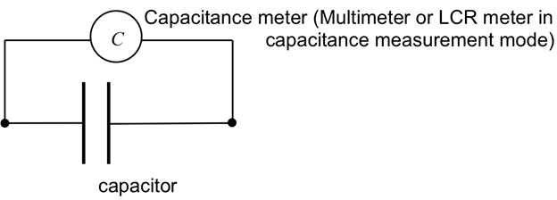
Figure 2: Diagram showing a capacitance meter connected to a capacitor to directly measure its capacitance.
Prosedür
1. Charging a Capacitor
- Obtain a commercial capacitor with capacitance C = 470 µF (or some similar value), a programmable voltage source, and an amp-meter (or multi-meter that can measure current).
- With the voltage source set to 0 V, connect the "+" terminal of the voltage source to one terminal of the capacitor, with the amp-meter in between, and connect the "−" terminal of the voltage source to the other terminal, as in Figure 1. The connection can be made with cables with clamps or banana plugs into receiving ports on the capacitor and instruments.
- Switch the voltage source from 0 V to 1 V (in about 1 s), and observe the transient current reading on the amp-meter. Do the same for 2 V, 5 V, and 10 V (for each target voltage; this means first go back to 0 V, then switch to the target voltage in about 1 s). Note that the transient current is larger for a larger target voltage, as expected from Equation 2.
- Program the voltage source to generate a voltage ramp from 0 V to 10 V in 5 s, and record the "steady state" reading of the amp-meter during the middle of the ramp. Repeat for a ramp time of 10 s, 20 s, and 30 s. Plot the observed current versus the voltage ramp rate (in V/s).
2. Tuning the Capacitance
- Turn off the voltage source and replace it with a 300 V battery, and replace the amp-meter by a 1 MΩ resistor (the purpose of this resistor is to provide extra protection to limit the current in the circuit); also replace the commercial capacitor with a parallel plate capacitor with an adjustable separation between the plates.
- Obtain a high-impedance voltmeter (or "electrometer") and connect it to measure the voltage difference V between the two plates (the high impedance impedes the discharge of the capacitor during the experiment when the electrometer is connected). See Figure 5.
- Connect the 300 V battery to the parallel plate capacitor, wait until the electrometer reaches the steady state of 300 V (now the capacitor is fully charged by the 300 V source), and then quickly disconnect the voltage source from the plates. See Figure 6. The electrometer should still read 300 V.
- Now increase the distance d between the plates to larger values such as 15 mm, 10 mm, and 5 mm, and observe and record the corresponding voltage reading on the electrometer (V); plot V versus d.
- Increase d back to ~ 20 mm, insert a plastic slab between the two plates and observe what happens to V read by the electrometer. The reduction of V between the plates (with charge Q fixed in this case) results from the larger dielectric constant ε of the plastic (compared to air) as the medium of the capacitor (refer to Equations 1 and 3).
3. Parallel and Series Capacitances
- Obtain a capacitance meter (a "LCR meter" or a multi-meter with a capacitance measurement mode); obtain a breadboard to facilitate the electrical connections in this part of the experiment.
- Obtain two commercial "ceramic" capacitors with a capacitance of 1 µF, and use the capacitance meter to verify their capacitance, as in Figure 2.
- Connect the two capacitors in parallel, and use the capacitance meter to measure the total capacitance (between points A and B, see Figure 3).
- Connect the two capacitors in series, and use the capacitance meter to measure the total capacitance (between points A and B, see Figure 4).

Figure 3: Diagram showing two capacitors connected in parallel.

Figure 4: Diagram showing two capacitors connected in series.

Figure 5: Diagram showing the charging up of a capacitor using a voltage source, while reading the voltage with an electrometer.

Figure 6: After quickly disconnecting the voltage source in Figure 5, the voltage and charge on the capacitor should remain.
Sonuçlar
For a capacitor, a plot of current I versus ramp rate ΔV/Δt is linear, as shown in Figure 7. Since the current is the rate of the change in the charge Q on one conductor terminal, this also reflects the linear relationship between charge Q and voltage V for a capacitor (Equation 1). The slope of the line is equal to the capacitance of the capacitor (Equation 2).
For a parallel plate capacitor with fixed charge Q, a plot of the voltage V between the plates versus the distance d between the plates should also be linear, as depicted in Figure 8. This verifies Equation 4, which is a consequence of the capacitance C of the parallel plate capacitor being inversely proportional to the distance d (Equation 3) and the voltage V being inversely proportional to the capacitance C (because the charge Q is fixed, Equation 1).
For two capacitors, each having 1 μF of capacitance, their parallel connection should give a total capacitance of 2 µF, and their series connection should measure a total capacitance of 0.5 µF, consistent with Equations 5 and 6 on the rules of combining capacitances in parallel or in series.

Figure 7: An exemplary linear plot between current and voltage ramp rate.

Figure 8: An exemplary linear plot between inter-plate voltage and distance.
Başvuru ve Özet
In this experiment, the charging of a capacitor was demonstrated, where the current is the product of the capacitance and the rate of change of voltage. By observing how the voltage varies given a fixed charge, we have demonstrated how the capacitance of a parallel plate capacitor varies with the separation and with the medium between the plates.
The capacitance meter can also be used to directly measure the capacitance, and determine the total capacitance for capacitors connected in parallel or in series.
Capacitors are commonly used in many circuit applications. They can be used to store charges and energy. They are essential for electrical signal processing. For example, taking the derivative of an electrical signal, so called the "differentiator", as the capacitor current, is directly proportional to the derivative of a time dependent voltage applied to the capacitor. They are also used in filters (the conduction between the two conductors making up a capacitor generally increases at higher frequency although it is very low at low frequency).
The author of the experiment acknowledges the assistance of Gary Hudson for material preparation and Chuanhsun Li for demonstrating the steps in the video.
Atla...
Bu koleksiyondaki videolar:

Now Playing
Capacitance
Physics II
43.8K Görüntüleme Sayısı

Electric Fields
Physics II
77.5K Görüntüleme Sayısı

Electric Potential
Physics II
105.0K Görüntüleme Sayısı

Magnetic Fields
Physics II
33.6K Görüntüleme Sayısı

Electric Charge in a Magnetic Field
Physics II
33.7K Görüntüleme Sayısı

Investigation Ohm's Law for Ohmic and Nonohmic Conductors
Physics II
26.2K Görüntüleme Sayısı

Series and Parallel Resistors
Physics II
33.2K Görüntüleme Sayısı

Inductance
Physics II
21.6K Görüntüleme Sayısı

RC/RL/LC Circuits
Physics II
142.9K Görüntüleme Sayısı

Semiconductors
Physics II
29.9K Görüntüleme Sayısı

Photoelectric Effect
Physics II
32.7K Görüntüleme Sayısı

Reflection and Refraction
Physics II
36.2K Görüntüleme Sayısı

Interference and Diffraction
Physics II
91.2K Görüntüleme Sayısı

Standing Waves
Physics II
49.8K Görüntüleme Sayısı

Sound Waves and Doppler Shift
Physics II
23.5K Görüntüleme Sayısı
JoVE Hakkında
Telif Hakkı © 2020 MyJove Corporation. Tüm hakları saklıdır