
干渉と回折
概要
ソース: 龍 p. 陳博士は、物理学科 & 天文学、科学の大学、パーデュー大学、ウェスト ラファイエット, インディアナ
干渉と回折波、水の波から光などの電磁波に至るまでの特徴的な現象であります。干渉は、大小の波の振幅の交流空間的変化を与える同じ種類の 2 つの波が重なっているときの現象を指します。回折波の開口部を通過またはオブジェクトの周り行くときの現象を指します、波のさまざまな部分が干渉できも大と小振幅の空間交替に上昇を与えます。
この実験はそれぞれ単一のスリットや二重スリットを通過するレーザー光の回折と干渉を観察することによって、光の波の性質を示します。スリットは、単にアルミ箔のかみそりの刃を使用してカットし、ホイルに slit(s) を介して光が輝いていたとき、箔の後に画面上の明るい部分と暗い縞を交互のパターンとして特徴的な回折と干渉パターンのマニフェストします。歴史的に、光の干渉と回折の観察は、光が電磁波であることを確立する重要な役割を果たした。
原則
A wave is an oscillation in the amplitude of some physical quantity in space and/or time. Waves or different parts of waves can overlap and “interfere” to produce an alternating strong and weak amplitude. Interference is one of the most characteristic phenomena associated with waves. Consider a simple example of two waves propagating along a one-dimension line (x-axis) and mathematically represented by:
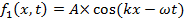
and,
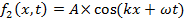
propagating to the right (+x direction) and left (−x direction), respectively. Here, A is the peak amplitude, and k is the “wave number” or “wave vector” defined as,

where λ is the wavelength (spatial periodicity of the wave). ω is defined as,

where f is the frequency and,

where T is the period (in time) of the wave. When the two waves overlap, their amplitudes add up (which is known as the “superposition principle of the wave”) to give:

which is also known as a “standing wave”. At those locations where,

(where n is an integer) and,

the oscillations (as functions of time t) will have maximal amplitude (between −2A and +2A). In contrast, at locations where,

and,

the oscillations will have zero (thus minimal) amplitude (also known as “nodes”). Such a spatial alternation of strong and weak wave amplitude represents an “interference pattern”. This phenomenon can be generalized to waves in two- and three-dimensional space. It also underlies the phenomena of single-slit diffraction and double-slit interference of light (which is an electromagnetic wave) to be observed in this experiment.
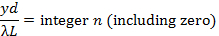
If the light of wavelength (λ) is shone on a narrow slit of width (a) (shown schematically in Figure 1a), the light intensity (which is proportional to the square of the peak amplitude of wave) far away from the slit will alternate between large and small (nearly zero) values, corresponding to “bright” and “dark” regions, along the width direction (“y-axis” in Figure 1a) of the slit. This alternation, known as the “diffraction pattern” of the light (through a small aperture), is also a characteristic phenomenon for waves. Fundamentally, it arises from the interference between different parts of the light wave after the aperture (in particular, points between the two edges of the aperture will “re-emit” the light wave towards different directions). The angular variation of the light intensity is denoted as I(θ), where θ represents the angle of the direction (towards +y or –y) away from the “straight through” direction, through y = 0 in Figure 1a). For small θ, it can be shown that I(θ) is approximately proportional to |sin(πaθ/λ)/(πaθ/λ)|2. That is, “dark” for,
and “bright for,
. If the screen is placed at distance L from the slit, alternating bright and dark fringes at different positions of y (each fringe will run parallel to the slit) are observed, as schematically shown in Figure 1b (left). For small θ (close to the center y = 0),
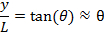
thus the fringes intensity can be approximately described as,

(this function is schematically shown in Figure 1b, right). The center y = 0 is always a bright fringe (since sin(t)/t has a maximum of 1 when t→0 and decreases monotonically down to 0 as t increases from 0 to π). Moving away from the center, the “first order” dark fringes are encountered centered at,

then bright fringes centered at,

then dark fringes again centered at,

Then bright fringes again centered at,

and so on. The width of each bright fringe outside the center is approximately λL/a, except for the central bright fringe which is twice as wide (width ~ 2λL/a, or the separation between two first-order dark fringes at ± λL/a). The narrower the slit, or the larger the wavelength λ or the screen distance L, the more spread-out the fringes will be.
If light is shone through two closely separated narrow slits with separation d (schematically depicted in Figure 2a) in an otherwise similar setup as in Figure 1, the famous “Young’s double slit interference pattern” can be observed (schematically shown in Figure 2b). It can be shown that for small θ (close to the center y = 0), bright fringes centered at,
and dark fringes centered at,

can be observed. In contrast to the single slit diffraction pattern discussed above, here all the light fringes (including the central one at y = 0), have equal widths and are equally spaced by λL/d. The narrow slits will still produce diffraction patterns, but usually the slit width (a) is much smaller than the separation (d), and the intensity modulation (due to the diffraction pattern) will superimpose on the much closer and equally spaced double-slit interference fringes.
The light source in the above discussion is assumed to be perfectly monochromatic (meaning it has one well defined-wavelength λ) and coherent (meaning if the instants that the wave oscillation reaches maximum or minimum at one location is known, the instants that the maximum or minimum will be reached at any other locations can be predicted). This is the case for example, if the wave is described by a cosine function as cos(kx−ωt+ϕ) with a uniform, constant phase ϕ, which can be chosen to be zero by redefining the starting point of time. Since a laser is the best approximation for this kind of ideal light source, a laser beam is used as the light source in this experiment (historically in the pre-laser time, such experiments have used a point-like light source such as that produced by passing light though a small hole).
It is important to note that the actual diffraction and interference fringes (including the shape and intensity of the fringes) can look more complicated and less “ideal” than those described above in these simplest cases and approximations, due to imperfections in the light source as well as in the slits. For example, the contrast of the fringes can be reduced (such that the “dark” fringes do not really reach zero intensity) if the light source is less coherent. On the other hand, the positions and spacing of the fringes are usually well-predicted by the simple model discussed above.
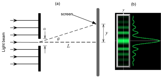
Figure 1: Single slit diffraction. (a) Schematic diagram of the optical setup, with light shining through a narrow slit of width a, and an observation screen located distance L away; and (b) Schematic diffraction fringe pattern that may be observed on the screen (left) and corresponding light intensity variation as function of vertical distance (y) away from the center.

Figure 2: Double slit interference. (a) Schematic diagram of the optical setup, with light shining through two narrow slits separated by distance d, and an observation screen located distance L away; and (b) Schematic interference fringes (equally spaced) that may be observed on the screen.
手順
1. 実験の必要なコンポーネントを取得
- レーザー安全メガネを入手してレーザーの電源を入れる前にこの実験中に着用します。
- アルミ箔の一部を入手して 2 つ (約) 2 x 2 の正方形の部分にそれをカットするはさみを使用します。
- 2 段ボール、それぞれ約 3 x 3、穴 (直径約 1 インチ) を途中でカットを取得します。
- 厚紙や段ボールすることができます録音するブロックをクランプすることができますデバイスを取得します。
- いくつかの薄いかみそりの刃を入手します。
- 波長と He-ne レーザー ポインターを取得 〜 532 の波長 633 nm またはグリーン レーザー ポインター nm。
2. 単スリット回折
- アルミ箔の正方形を取り、かみそりの刃を使用して、スリット ホイルの真ん中に約 1 cm 長い。ストレート カットを取得するのにかみそりを導くために、ルーラーを使用します。
- (図 3 aに示す) オープン穴の内側水平方向にスリット入り段ボール広場に箔をテープします。箔のコーナーの周りのテープを置く (スリットをカバーして)。段ボールは、この実験中に箔を安定させるのに役立ちます。段ボールの 1 つの端をクランプ デバイス (段ボールがテーブルの表面に垂直にする必要があります)、穴と水平スリット (画面になる)、白い壁に直面して、約 30 cm 離れて。
- レーザー ポインターをオンにし、スリット上にレーザービーム (箔に垂直な方向に伝搬する) を当てます。箔の反対側の壁に光のパターンを観察します。パターンのよりよい可視性のため室内灯の電源を切ります。
3. 二重スリット干渉
- その他のアルミ箔を取る。3 かみそりの刃を一緒にスタックが、中間のブレードとエッジの他の 2 つのブレードのエッジから凹んでいます。箔 (それぞれ約 1 cm 長い) の途中で 2 つの密接に間隔のスリットをカットするのにこのスタックを使用します。定規を使用してかみそりをガイドし、ストレート カット。
- (図 4 aに示す)、他の段ボールに箔のテープし、再び副またはブロック、2.2 の手順と同様に段ボールをサポートします。
- レーザー ポインターをオンにし、二重スリットにレーザービームを当てます。箔の反対側の壁に光のパターンを観察します。パターンのよりよい可視性のため室内灯の電源を切ります。
結果
ステップ 2.3、壁に観察することができる代表的な光のパターンが表示されます図 3 bで特徴的な回折縞を出展します。中央の明るいフリンジの幅の約 2 倍であることに注意してください ( y-方向) (ほぼ同じ幅である) 他の明るい縞として、 yに沿って中心から明るい縞崩壊輝度-軸、単スリット回折パターンどおり。
ステップ 3.3、図 4 bで壁に観察することができる代表的な光のパターンが表示されます。手順 2.3 回折パターンに似た全体的な強度変調パターンがあります。これは確かにそれぞれの狭いスリットによる回折パターンです。回折パターンの明るい領域、内 1 つはおよそ均等に間隔をあけられた鮮やかなストライプを観察できます。これらは、二重スリット干渉縞です。これらの干渉縞は、間スリット分離dは、スリット幅、 (これらの長さの逆数は、回折や干渉縞の幅をそれぞれ制御) よりもはるかに大きいため回折パターンの明るい領域よりもはるかに狭くなります。

図 3.図: 侮; と段ボールに固定されているアルミ箔の単一スリット (、) レーザー光輝く(b) 代表的な回折縞がスリット後画面で観察.
図 4 。図: (、) レーザーのビームを侮; と段ボールに固定されているアルミ箔の 2重スリットの上で輝いて二重スリット後画面上 (b) 代表的な干渉縞が観察されました。
申請書と概要
この実験ではレーザー光を用いた単一スリット回折パターンと光の二重スリット干渉パターン実証も我々。これらの特徴的な波動現象を観察、光の波の性質を示しています。
光の干渉と回折は、光が電磁波であることを確立を助けた、光学系の開発で重要な役割を果たした。これらの効果はまた光学及びフォトニクスに基づくさまざまな技術の重要です。たとえば、小さなオブジェクトまたは小さな穴のサイズを測定する回折を用いありも際に考慮すべき重要な面光学顕微鏡の設計画像処理システム。(いわゆる「干渉」) 光の干渉の測定は (光源や鏡の間など) の距離の精密測定に使用できます、加工、地質学、天文学 (重力波を検出 LIGO プロジェクトなど) からアプリケーションを発見しました。
実験の著者は、材料準備のためゲイリー ハドソンとビデオの手順を示すため Chuanhsun Li の支援を認めています。
タグ
スキップ先...
このコレクションのビデオ:

Now Playing
干渉と回折
Physics II
91.7K 閲覧数

電界
Physics II
77.8K 閲覧数

電位
Physics II
105.6K 閲覧数

磁場
Physics II
33.8K 閲覧数

磁場下における電荷
Physics II
33.8K 閲覧数

オームの法則
Physics II
26.4K 閲覧数

シリーズと並列抵抗
Physics II
33.3K 閲覧数

静電容量
Physics II
43.9K 閲覧数

インダクタンス
Physics II
21.7K 閲覧数

RC/RL/LC 回路
Physics II
143.3K 閲覧数

半導体
Physics II
30.3K 閲覧数

光電効果
Physics II
32.9K 閲覧数

反射と屈折
Physics II
36.4K 閲覧数

定在波
Physics II
50.0K 閲覧数

音の波とドップラー シフト
Physics II
23.6K 閲覧数
Copyright © 2023 MyJoVE Corporation. All rights reserved