
Interferencia y difracción
Visión general
Fuente: Yong P. Chen, PhD, Departamento de física & Astronomía, Facultad de Ciencias, Universidad de Purdue, West Lafayette, IN
Interferencia y la difracción son fenómenos característicos de las ondas, desde ondas de agua a las ondas electromagnéticas como la luz. Interferencia se refiere al fenómeno de cuando se superponen dos ondas de la misma clase para dar una variación espacial alterna de amplitud de onda de grandes y pequeños. Difracción se refiere al fenómeno de cuando una onda pasa a través de una abertura o va alrededor de un objeto, diferentes partes de la onda pueden interferir y también dar lugar a una alternancia espacial de amplitud grande y pequeño.
Este experimento demostrará la naturaleza de onda de la luz mediante la observación de la difracción y la interferencia de la luz láser pasa a través de una sola ranura y las aberturas doble, respectivamente. Las ranuras se cortan simplemente utilizando cuchillas de afeitar en una lámina de aluminio y los patrones de difracción y la interferencia característicos se manifiestan como patrones de alternancia de franjas claras y oscuras en una pantalla colocada después de la hoja, cuando la luz se brilla a través de la slit(s) en la hoja. Históricamente, la observación de la difracción y la interferencia de la luz jugaron papeles importantes en el establecimiento de que la luz es una onda electromagnética.
Principios
A wave is an oscillation in the amplitude of some physical quantity in space and/or time. Waves or different parts of waves can overlap and “interfere” to produce an alternating strong and weak amplitude. Interference is one of the most characteristic phenomena associated with waves. Consider a simple example of two waves propagating along a one-dimension line (x-axis) and mathematically represented by:
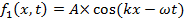
and,
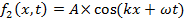
propagating to the right (+x direction) and left (−x direction), respectively. Here, A is the peak amplitude, and k is the “wave number” or “wave vector” defined as,

where λ is the wavelength (spatial periodicity of the wave). ω is defined as,

where f is the frequency and,

where T is the period (in time) of the wave. When the two waves overlap, their amplitudes add up (which is known as the “superposition principle of the wave”) to give:

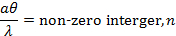
which is also known as a “standing wave”. At those locations where,

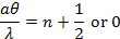
(where n is an integer) and,

the oscillations (as functions of time t) will have maximal amplitude (between −2A and +2A). In contrast, at locations where,

and,

the oscillations will have zero (thus minimal) amplitude (also known as “nodes”). Such a spatial alternation of strong and weak wave amplitude represents an “interference pattern”. This phenomenon can be generalized to waves in two- and three-dimensional space. It also underlies the phenomena of single-slit diffraction and double-slit interference of light (which is an electromagnetic wave) to be observed in this experiment.
If the light of wavelength (λ) is shone on a narrow slit of width (a) (shown schematically in Figure 1a), the light intensity (which is proportional to the square of the peak amplitude of wave) far away from the slit will alternate between large and small (nearly zero) values, corresponding to “bright” and “dark” regions, along the width direction (“y-axis” in Figure 1a) of the slit. This alternation, known as the “diffraction pattern” of the light (through a small aperture), is also a characteristic phenomenon for waves. Fundamentally, it arises from the interference between different parts of the light wave after the aperture (in particular, points between the two edges of the aperture will “re-emit” the light wave towards different directions). The angular variation of the light intensity is denoted as I(θ), where θ represents the angle of the direction (towards +y or –y) away from the “straight through” direction, through y = 0 in Figure 1a). For small θ, it can be shown that I(θ) is approximately proportional to |sin(πaθ/λ)/(πaθ/λ)|2. That is, “dark” for,
and “bright for,
. If the screen is placed at distance L from the slit, alternating bright and dark fringes at different positions of y (each fringe will run parallel to the slit) are observed, as schematically shown in Figure 1b (left). For small θ (close to the center y = 0),
thus the fringes intensity can be approximately described as,

(this function is schematically shown in Figure 1b, right). The center y = 0 is always a bright fringe (since sin(t)/t has a maximum of 1 when t→0 and decreases monotonically down to 0 as t increases from 0 to π). Moving away from the center, the “first order” dark fringes are encountered centered at,

then bright fringes centered at,

then dark fringes again centered at,

Then bright fringes again centered at,

and so on. The width of each bright fringe outside the center is approximately λL/a, except for the central bright fringe which is twice as wide (width ~ 2λL/a, or the separation between two first-order dark fringes at ± λL/a). The narrower the slit, or the larger the wavelength λ or the screen distance L, the more spread-out the fringes will be.
If light is shone through two closely separated narrow slits with separation d (schematically depicted in Figure 2a) in an otherwise similar setup as in Figure 1, the famous “Young’s double slit interference pattern” can be observed (schematically shown in Figure 2b). It can be shown that for small θ (close to the center y = 0), bright fringes centered at,
and dark fringes centered at,

can be observed. In contrast to the single slit diffraction pattern discussed above, here all the light fringes (including the central one at y = 0), have equal widths and are equally spaced by λL/d. The narrow slits will still produce diffraction patterns, but usually the slit width (a) is much smaller than the separation (d), and the intensity modulation (due to the diffraction pattern) will superimpose on the much closer and equally spaced double-slit interference fringes.
The light source in the above discussion is assumed to be perfectly monochromatic (meaning it has one well defined-wavelength λ) and coherent (meaning if the instants that the wave oscillation reaches maximum or minimum at one location is known, the instants that the maximum or minimum will be reached at any other locations can be predicted). This is the case for example, if the wave is described by a cosine function as cos(kx−ωt+ϕ) with a uniform, constant phase ϕ, which can be chosen to be zero by redefining the starting point of time. Since a laser is the best approximation for this kind of ideal light source, a laser beam is used as the light source in this experiment (historically in the pre-laser time, such experiments have used a point-like light source such as that produced by passing light though a small hole).
It is important to note that the actual diffraction and interference fringes (including the shape and intensity of the fringes) can look more complicated and less “ideal” than those described above in these simplest cases and approximations, due to imperfections in the light source as well as in the slits. For example, the contrast of the fringes can be reduced (such that the “dark” fringes do not really reach zero intensity) if the light source is less coherent. On the other hand, the positions and spacing of the fringes are usually well-predicted by the simple model discussed above.
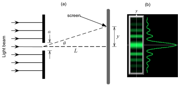
Figure 1: Single slit diffraction. (a) Schematic diagram of the optical setup, with light shining through a narrow slit of width a, and an observation screen located distance L away; and (b) Schematic diffraction fringe pattern that may be observed on the screen (left) and corresponding light intensity variation as function of vertical distance (y) away from the center.

Figure 2: Double slit interference. (a) Schematic diagram of the optical setup, with light shining through two narrow slits separated by distance d, and an observation screen located distance L away; and (b) Schematic interference fringes (equally spaced) that may be observed on the screen.
Procedimiento
1. adquirir los componentes necesarios para el experimento
- Obtener gafas láser y vestir durante este experimento antes de encender el láser.
- Obtener un pedazo de papel de aluminio y utilizar tijeras para cortar en dos trozos cuadrados de 2 x 2 (aproximadamente).
- Obtener dos cartulinas, cada uno de aproximadamente 3 x 3, con un agujero (diámetro de aproximadamente 1 en) cortadas en el medio.
- Obtener un dispositivo que puede sujetar la cartulina o un block para que el cartón puede ser grabado.
- Obtener unas finas hojas de afeitar.
- Obtener un puntero de láser de He-Ne con longitud de onda de ~ 633 nm o verde puntero de láser con longitud de onda de 532 nm.
2. solo raja difracción
- Tomar un cuadrado de papel de aluminio y utilice una cuchilla para cortar una ranura alrededor de 1 cm de largo en el centro de la hoja. Use una regla para ayudar a guiar la afeitadora para obtener un corte recto.
- Pegue la lámina sobre un cuadrado de cartón con la abertura orientada horizontalmente dentro del agujero abierto (esquemáticamente se muestra en la figura 3a). Poner cinta en las esquinas de la lámina (no cubra la ranura). El cartón ayuda a estabilizar la hoja durante este experimento. Sujete un extremo de la cartulina con el dispositivo (el cartón debe ser perpendicular a la superficie de la mesa), con el agujero y ranura horizontal expuesto y frente a una pared blanca (que será la pantalla) unos 30 cm de distancia.
- Encender el puntero láser y el brillo del haz de láser (propagación en dirección normal a la lámina) en la ranura. Observar el patrón de luz en la pared en el otro lado de la hoja. Apagar la sala de luz para mejor visibilidad del patrón.
3. doble ranura interferencia
- Tomar el otro papel de aluminio. Apilar las hojas de afeitar 3 juntos pero con la hoja media del borde empotrado de los bordes de los otros dos blades. Utilice esta pila para cortar dos ranuras de espaciamiento en el centro de la hoja (de cada uno de aproximadamente 1 cm). Utilice una regla para ayudar a guiar la maquinilla de afeitar y un corte recto.
- Cinta de papel sobre el otro cartón (esquemáticamente se muestra en la figura 4a) y otra vez la ayuda la cartulina con el vice o el bloque, similar al paso 2.2.
- Encender el puntero láser y brillar el rayo láser sobre la doble rendija. Observar el patrón de luz en la pared en el otro lado de la hoja. Apagar la sala de luz para mejor visibilidad del patrón.
Resultados
Paso 2.3, un patrón de luz representativo que se puede observar en la pared se muestra en la figura 3b, exhibiendo las franjas de difracción característico. Tenga en cuenta que la franja brillante central es aproximadamente dos veces tan amplia (en la y-dirección) como las otras franjas brillantes (que son casi lo mismo en anchura) y la sobre intensidad de la decadencia de flecos brillantes desde el centro a lo largo de la y-eje, como se esperaba para el patrón de difracción de la raja solo.
Paso 3.3, un patrón de luz representativo que se puede observar en la pared se muestra en la Figura 4b. Hay un patrón general de modulación de intensidad similar del patrón de difracción observado en el paso 2.3. Este hecho es el patrón de difracción debido a cada una de las ranuras estrechas. Dentro de las regiones brillantes del patrón de difracción, se pueden observar aproximadamente igualmente espaciados rayas brillantes. Estas son las franjas de interferencia de la doble rendija. Estas franjas de interferencia son mucho más estrechos que las regiones brillantes del patrón de difracción debido a la separación entre raja d es mucho más grande que la abertura ancho un (el recíproco de estas longitudes controlar el ancho de las franjas de interferencia o difracción, respectivamente).

Figura 3. Esquema: (un) un haz de láser brillante en un solo corte en papel de aluminio, que se fija en la cartulina con un agujero abierto; y (b) franjas de difracción representante observaron en una pantalla después de la abertura.
Figura 4. Esquema: (un) un laser viga en doble aberturas en aluminio, que se fija en la cartulina con un agujero abierto; y (b) franjas de interferencia representante observaron en una pantalla tras las rendijas dobles.
Aplicación y resumen
En este experimento, hemos demostrado el patrón de difracción de la raja sola y el patrón de interferencia de doble rendija de luz, con un rayo láser. Observando estos fenómenos característicos de la onda demuestra la naturaleza de onda de la luz.
La difracción y la interferencia de la luz jugaron papeles esenciales en el desarrollo de la óptica como ayudaron a establecer que la luz es una onda electromagnética. Estos efectos también son importantes en muchas tecnologías basadas en la óptica y la fotónica. Por ejemplo, la difracción se utiliza habitualmente para medir el tamaño de un objeto pequeño o pequeños agujeros, y es también un aspecto importante a considerar al diseñar microscopios ópticos y sistemas de imágenes. Medición de interferencia óptica (los llamados "interferometría") puede ser utilizado para la medición de distancias (como las fuentes de luz o espejos) y han encontrado aplicaciones de mecanizado, la geología y la astronomía (tal como en el proyecto LIGO que detectar las ondas gravitacionales).
El autor del experimento agradece la ayuda de Gary Hudson para la preparación de material y Chuanhsun Li para la demostración de los pasos en el video.
Tags
Saltar a...
Vídeos de esta colección:

Now Playing
Interferencia y difracción
Physics II
91.5K Vistas

Campos eléctricos
Physics II
77.7K Vistas

Potencial eléctrico
Physics II
105.4K Vistas

Campos magnéticos
Physics II
33.7K Vistas

Carga eléctrica en un campo magnético
Physics II
33.7K Vistas

Ley de Ohm
Physics II
26.3K Vistas

Resistencias en serie y en paralelo
Physics II
33.2K Vistas

Capacitancia
Physics II
43.9K Vistas

Inductancia
Physics II
21.7K Vistas

Circuitos RC/RL/LC
Physics II
143.2K Vistas

Semiconductores
Physics II
30.0K Vistas

Efecto fotoeléctrico
Physics II
32.8K Vistas

Reflexión y refracción
Physics II
36.4K Vistas

Ondas estacionarias
Physics II
50.0K Vistas

Ondas sonoras y efecto Doppler
Physics II
23.5K Vistas
ACERCA DE JoVE
Copyright © 2025 MyJoVE Corporation. Todos los derechos reservados