干涉和衍射
Overview
资料来源: 陈博士体育永,物理系 & 天文学、 科技大学、 普渡大学、 西拉斐特,在
干涉和衍射是波,从水波到电磁波,比如光的特征现象。干扰是指当两个波的同一种重叠给大型和小型波振幅交替的空间变化的现象。衍射是指当波通过孔径或绕着对象的现象,干扰,也给大、 小振幅空间交替上升可以波的不同部分。
本实验将通过观察衍射和激光光分别通过单缝和双缝干涉演示光的波动性。这两条缝索性在铝箔用锋利的刀片和衍射和干涉的特征,表现为交替放置后铝箔,当光线照在铝箔上 slit(s) 的屏幕上的光与暗条纹的图案。从历史上看,光的干涉和衍射观察发挥了重要作用建立光一种电磁波。
Principles
A wave is an oscillation in the amplitude of some physical quantity in space and/or time. Waves or different parts of waves can overlap and “interfere” to produce an alternating strong and weak amplitude. Interference is one of the most characteristic phenomena associated with waves. Consider a simple example of two waves propagating along a one-dimension line (x-axis) and mathematically represented by:
and,
propagating to the right (+x direction) and left (−x direction), respectively. Here, A is the peak amplitude, and k is the “wave number” or “wave vector” defined as,

where λ is the wavelength (spatial periodicity of the wave). ω is defined as,

where f is the frequency and,

where T is the period (in time) of the wave. When the two waves overlap, their amplitudes add up (which is known as the “superposition principle of the wave”) to give:

which is also known as a “standing wave”. At those locations where,

(where n is an integer) and,

the oscillations (as functions of time t) will have maximal amplitude (between −2A and +2A). In contrast, at locations where,

and,

the oscillations will have zero (thus minimal) amplitude (also known as “nodes”). Such a spatial alternation of strong and weak wave amplitude represents an “interference pattern”. This phenomenon can be generalized to waves in two- and three-dimensional space. It also underlies the phenomena of single-slit diffraction and double-slit interference of light (which is an electromagnetic wave) to be observed in this experiment.
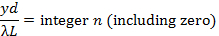
If the light of wavelength (λ) is shone on a narrow slit of width (a) (shown schematically in Figure 1a), the light intensity (which is proportional to the square of the peak amplitude of wave) far away from the slit will alternate between large and small (nearly zero) values, corresponding to “bright” and “dark” regions, along the width direction (“y-axis” in Figure 1a) of the slit. This alternation, known as the “diffraction pattern” of the light (through a small aperture), is also a characteristic phenomenon for waves. Fundamentally, it arises from the interference between different parts of the light wave after the aperture (in particular, points between the two edges of the aperture will “re-emit” the light wave towards different directions). The angular variation of the light intensity is denoted as I(θ), where θ represents the angle of the direction (towards +y or –y) away from the “straight through” direction, through y = 0 in Figure 1a). For small θ, it can be shown that I(θ) is approximately proportional to |sin(πaθ/λ)/(πaθ/λ)|2. That is, “dark” for,
and “bright for,
. If the screen is placed at distance L from the slit, alternating bright and dark fringes at different positions of y (each fringe will run parallel to the slit) are observed, as schematically shown in Figure 1b (left). For small θ (close to the center y = 0),
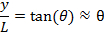
thus the fringes intensity can be approximately described as,

(this function is schematically shown in Figure 1b, right). The center y = 0 is always a bright fringe (since sin(t)/t has a maximum of 1 when t→0 and decreases monotonically down to 0 as t increases from 0 to π). Moving away from the center, the “first order” dark fringes are encountered centered at,

then bright fringes centered at,

then dark fringes again centered at,

Then bright fringes again centered at,

and so on. The width of each bright fringe outside the center is approximately λL/a, except for the central bright fringe which is twice as wide (width ~ 2λL/a, or the separation between two first-order dark fringes at ± λL/a). The narrower the slit, or the larger the wavelength λ or the screen distance L, the more spread-out the fringes will be.
If light is shone through two closely separated narrow slits with separation d (schematically depicted in Figure 2a) in an otherwise similar setup as in Figure 1, the famous “Young’s double slit interference pattern” can be observed (schematically shown in Figure 2b). It can be shown that for small θ (close to the center y = 0), bright fringes centered at,
and dark fringes centered at,

can be observed. In contrast to the single slit diffraction pattern discussed above, here all the light fringes (including the central one at y = 0), have equal widths and are equally spaced by λL/d. The narrow slits will still produce diffraction patterns, but usually the slit width (a) is much smaller than the separation (d), and the intensity modulation (due to the diffraction pattern) will superimpose on the much closer and equally spaced double-slit interference fringes.
The light source in the above discussion is assumed to be perfectly monochromatic (meaning it has one well defined-wavelength λ) and coherent (meaning if the instants that the wave oscillation reaches maximum or minimum at one location is known, the instants that the maximum or minimum will be reached at any other locations can be predicted). This is the case for example, if the wave is described by a cosine function as cos(kx−ωt+ϕ) with a uniform, constant phase ϕ, which can be chosen to be zero by redefining the starting point of time. Since a laser is the best approximation for this kind of ideal light source, a laser beam is used as the light source in this experiment (historically in the pre-laser time, such experiments have used a point-like light source such as that produced by passing light though a small hole).
It is important to note that the actual diffraction and interference fringes (including the shape and intensity of the fringes) can look more complicated and less “ideal” than those described above in these simplest cases and approximations, due to imperfections in the light source as well as in the slits. For example, the contrast of the fringes can be reduced (such that the “dark” fringes do not really reach zero intensity) if the light source is less coherent. On the other hand, the positions and spacing of the fringes are usually well-predicted by the simple model discussed above.
Figure 1: Single slit diffraction. (a) Schematic diagram of the optical setup, with light shining through a narrow slit of width a, and an observation screen located distance L away; and (b) Schematic diffraction fringe pattern that may be observed on the screen (left) and corresponding light intensity variation as function of vertical distance (y) away from the center.

Figure 2: Double slit interference. (a) Schematic diagram of the optical setup, with light shining through two narrow slits separated by distance d, and an observation screen located distance L away; and (b) Schematic interference fringes (equally spaced) that may be observed on the screen.
Procedure
1.为实验获得所需的组件
- 获得激光护目镜和穿之前打开激光实验过程中。
- 获得一块铝箔,再用剪刀把它切成两个 (大约) 2 × 2 的正方形块。
- 获得两个纸板,每个大约 3 x 3 中,孔 (直径大约 1 英寸),中间穿。
- 获取可夹纸板或块纸板可以录音的设备。
- 获得几个薄刀片。
- 获取与波长的氦-氖激光指针 ~ 633 nm 或绿色激光指针与波长 532 nm。
2.单缝衍射
- 处理铝铝箔广场,用刀片,切缝大约 1 厘米长在金属箔。使用一把尺子来帮助指导剃刀获得直切。
- 带缝 (示意图见图 3a) 的开孔内水平面向磁带铝箔纸板的广场上。把铝箔转弯磁带 (不包括缝)。纸板有助于稳定在这个实验中的金属箔。夹一个边缘的纸板 (纸板应垂直于桌子的表面) 的设备,与孔和水平缝暴露,并面临着白色的墙 (这将是屏幕) 约 30 公分以上的距离。
- 打开激光指针,闪耀激光光束 (在垂直于铝箔的方向) 到狭缝。观察光模式在铝箔的另一边的墙上。关掉房间里的灯光模式更加清晰可见。
3.双缝干涉
- 采取其他铝箔。堆栈 3 刀片在一起,但与中间叶片的边缘嵌从其他两个叶片的边缘。用此堆栈切两个近距狭缝在铝箔 (每个大约 1 厘米长)。用一把尺子,帮助指导剃刀,使直切。
- 磁带上其他纸板 (简图中图 4a所示) 箔和再次支持与副或块,类似于步骤 2.2 纸板。
- 打开激光指针,照耀到双缝的激光束。观察光模式在铝箔的另一边的墙上。关掉房间里的灯光模式更加清晰可见。
Results
对于步骤 2.3,代表性的光纹在墙上将会观察到所示图 3b,参展特征衍射条纹。注意中央亮条纹是大约两倍宽 (在y-方向) 作为其他明亮条纹 (这是在宽度差不多),和超出强度的明亮的条纹衰变至中心沿y-轴,按预期的单缝衍射图样。
对于步骤 3.3,代表性的光纹在墙上将会观察到图 4b所示。还有一种整体的强度调制模式,看起来类似于在步骤 2.3 中观察到的衍射图样。这确实是由于每一条细缝的衍射图样。里面的衍射图样明亮的区域,一个可以观察大约同样间隔明亮条纹。这些都是双缝干涉条纹。这些干涉条纹是比明亮的区域的衍射图样的狭窄得多,因为间缝分离d是要远远大于狭缝宽度(这些长度的倒数分别控制干扰或衍射条纹,宽度)。

图 3.图中显示: () 激光束照耀着单缝对铝箔,固定在纸板与开孔;和 (b) 代表衍射条纹后缝观察屏幕上。
图 4。图中显示: () 的激光束照耀着双缝对铝箔,固定在纸板与开孔;和 (b) 代表干涉条纹后双缝观察屏幕上。
Application and Summary
在这个实验中,我们表明单缝衍射图样和双缝干涉条纹的光,用一束激光。观察这些特征波现象演示光的波动性。
光的干涉与衍射光学的发展中发挥重要作用,因为他们帮助建立了光是一种电磁波。基于光学和光子学的很多技术,也是这些影响。例如,衍射一般用来测量一个小物体或小破洞,大小和是也时要考虑的一个重要方面设计光学显微镜成像系统。(所以称为"干涉") 的光学干涉测量可以用于精密测量的距离 (如光源或镜子之间) 和发现从加工、 地质、 和天文学 (如探测到引力波的 LIGO 计) 的应用程序。
实验的作者承认援助的加里 · 哈德逊的材料制备和 Chuanhsun 李演示视频中的步骤。
Tags
跳至...
此集合中的视频:

Now Playing
干涉和衍射
Physics II
91.2K Views

电场
Physics II
77.5K Views

电势
Physics II
104.9K Views

磁场
Physics II
33.6K Views

电荷在磁场中
Physics II
33.7K Views

欧姆定律
Physics II
26.2K Views

系列和并联电阻
Physics II
33.2K Views

电容
Physics II
43.8K Views

电感
Physics II
21.6K Views

RC/RL/LC 电路
Physics II
142.9K Views

半导体
Physics II
29.8K Views

光电效应
Physics II
32.7K Views

反射和折射
Physics II
36.2K Views

驻波
Physics II
49.8K Views

声波和多普勒频移
Physics II
23.4K Views
版权所属 © 2025 MyJoVE 公司版权所有,本公司不涉及任何医疗业务和医疗服务。