Reflection and Refraction
Overview
Source: Derek Wilson, Asantha Cooray, PhD, Department of Physics & Astronomy, School of Physical Sciences, University of California, Irvine, CA
Light travels at different speeds depending on the material through which it is propagating. When light travels from one material to another, it will either slow down or speed up. In order to conserve energy and momentum, the light must change the direction in which it propagates. This bending of light is known as refraction. Some fraction of the light is also reflected at the interface between the two materials. In special cases, a light beam can be refracted so sharply at an interface that it is actually completely reflected back into the medium from which it was coming.
Lenses make use of the principle of refraction. Lenses come in two varieties with different curvatures: convex lenses and concave lenses. Convex lenses are often used to focus light but can also be used to create magnified images of objects. When a convex lens causes the light rays coming from an object to diverge, the human eye judges the light to be coming from some point behind the actual object from which the light is originating. The image of the object will in this case be magnified. This type of image is called a virtual image. Concave lenses can also cause light rays to diverge and create virtual images, though the image will be demagnified.
This lab will demonstrate the fundamental law of refraction and will examine the ways in which lenses create images.
Principles
When light hits the interface between two materials, it is bent by some angle that depends on the composition of the two materials. At the boundary, the speed at which the light propagates changes, causing its direction of propagation to change as well. Each medium has a characteristic “index of refraction” that is defined as the ratio between the speed of light in vacuum and the speed of light in the medium:

where n is the dimensionless index of refraction, c is the speed of light in vacuum in meters per second (m/s), and v is the speed of light in the medium in meters per second (m/s). Light travels more slowly in a medium with a high index of refraction and more quickly in a medium with a low index of refraction.
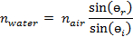
For a given angle of incidence, өi (angle at which the light hits the boundary between the two media), the angle at which the light beam is refracted, өr, is given by the Law of Refraction, which is more commonly known as Snell’s Law:

where өi and өr are in degrees, and n1 and n2 are the dimensionless indices of refraction of the initial and final materials through which the light is traveling. The refraction angle specifies the direction in which the refracted light wave will travel in the second medium (see Figure 1). Some fraction of the incident light is also reflected back into the first medium at an angle equal to the angle of incidence.
An interesting phenomenon occurs when light goes from a material with a high index of refraction to one with a lower index. There is a critical incident angle at which the refracted angle will become 90°. If light hits the boundary at the critical angle, the refracted beam will travel along the boundary between the media, and some light will be reflected back into the high index of refraction material (see Figure 2). If light hits the boundary at an angle greater than this critical angle, it will be completely reflected back into the high index of refraction material in an event called total internal reflection.

Figure 1: An incident light ray on the boundary between two media results in a reflected ray and a refracted ray.
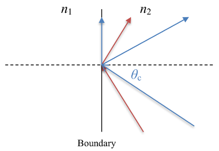
Figure 2: Total internal reflection when n2 > n1. The blue ray is incident at the critical angle and results in a refracted ray traveling along the interface and a reflected ray. The red ray is incident at an angle larger than the critical angle and leads to a totally internally reflected ray.
Lenses take advantage of refraction to create real and virtual images of objects. A real image is an image formed by the physical convergence of light rays that came from an object. A virtual image is formed when light rays appear to converge but do not actually physically converge. Our eyes construct a point of origin for diverging rays, and this point of origin serves as the source of the virtual images even though the light rays do not actually converge at this point. Examples of real and virtual images formed by a convex lens are shown in Figure 3. Lenses have a characteristic length called the “focal length”, which is the distance from the lens at which the light rays originating infinitely far away will be focused after passing through the lens. Given the focal length of a lens, the distance between the object and the lens will determine the location of the image according to the thin lens equation:

Where f is the focal length of the lens in meters (m), o is the distance between the lens and object in meters (m), and i is the distance between the lens and image in meters (m). If the object distance is taken to be a positive quantity, then, if the image distance is positive, the image will be real and will be located on the side of the lens opposite to the object. If the image distance is negative, the image will be virtual, magnified, and located on the same side of the lens as the object.
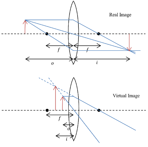
Figure 3: A convex lens producing real and virtual images. Real images form from the true convergence of light rays. Virtual images are constructed by our eyes from diverging light rays.
Procedure
1. Determine the index of refraction of water using Snell’s Law (Law of Refraction) and find the critical angle for total internal reflection.
- Obtain a specialized refraction tank with a light source.
- Fill the refraction tank with water and turn on the light source. Direct the beam from the light source into the half of the tank filled with water. It may be necessary to dim the lights in the room.
- Use the protractor on the refraction tank to measure the beam’s angle of incidence (the angle measured in the half of the tank filled with water) and angle of refraction (the angle measured in the half of the tank filled with air) for the water-air interface in the tank.
- Use the measured angles and the index of refraction for air (nair = 1.00) to calculate the index of refraction for water.
- Repeat the previous steps for a few incident angles varying from 0° to just under 90°.
- As the incident angle is increased, one will notice that the refracted light beam can no longer be seen in the half of the container containing air. Slowly rotate the light source about the tank until the point at which the light beam first disappears from the air is reached. This is the critical angle for total internal reflection.
- If the light source is further rotated, it should be observed that the beam reflects back into the water.
- Move the light source so that the beam enters the half of the tank filled with air first before traveling into the water. Record a few angles of incidence and refraction under this condition. Note that, previously, the angle of incidence was the angle at which the light traveled through the water. Since the light is now going through the air first, the new angle of incidence is the angle at which it travels through the air, and the new angle of refraction is the angle at which it travels through the water.
- Observe that total internal reflection does not occur in this configuration. Total internal reflection only occurs when light goes from a medium with a high index of refraction to a medium with a lower index of refraction.
2. Measure the focal length of a lens and create real and virtual images of an object.
- Obtain a convex lens, a concave lens, a sheet of white paper, a ruler, and a small distinctive object. It also helps to have an optical bench with holders for the lenses and object as well as an apparatus to hold the sheet of paper vertically.
- Place the convex lens between the object and the piece of paper, all in a line and at the same height.
- Move the object and paper around until a sharp image of the object appears on the paper. The image on the paper is a real image.
- Measure the distance from the lens to the object and the distance from the lens to the paper. Use the thin lens equation to determine the focal length of the lens.
- Place the paper aside and move the object closer to the lens until the distance between the lens and object is less than the focal length of the lens.
- Look through the lens: a magnified version of the object should be seen. This image is a virtual image.
- Replace the convex lens with the concave lens. Look through the concave lens: now a demagnified version of the object is visible. This is also a virtual image.
Results
Snell’s Law dictates the angle at which light will be bent when crossing the boundary between two media. The measured incident and refracted angles at the water-air interface are given in Table 1. Below, a sample calculation giving the index of refraction for water using Snell’s Law is shown for an angle of incidence equal to 30.1° as the light goes from the water to air:


 1.33
1.33
The calculation can be repeated for the various angles in Table 1, and the average of the measurements will provide an even better measurement of the index of refraction than any of the individual measurements will provide.
Table 1: Results.
| Interface | өi | өr | nwater |
| Water → Air | 10.0 | 13.5 | 1.34 |
| Water → Air | 19.8 | 26.6 | 1.32 |
| Water → Air | 30.1 | 41.9 | 1.33 |
| Air → Water | 20.1 | 15.1 | 1.32 |
| Air → Water | 44.9 | 32.0 | 1.33 |
| Air → Water | 75.2 | 46.7 | 1.33 |
The critical angle for total internal reflection occurs when the refraction angle is equal to 90°. For the water-air interface, Snell’s Law predicts that the critical angle of incidence is 48.8°.
It is worthwhile to note that the refracted beam could still be observed at an angle greater than 48.8° when looking at the interface at which the light beam went from air into the water. It is only at the boundary at which the beam went from the water to the air that the beam was internally reflected at angles greater than 48.8°. Total internal reflection can only occur when light goes from a medium with a high index of refraction to a medium with a lower index of refraction.
For the lens part of the experiment, when the object was placed at about o = 11.02 cm, the image came into focus at about 9.21 cm. The thin lens equation then reveals the focal length of the convex lens to be about 5.02 cm.
Application and Summary
This lab explores the physics of refraction and lenses. Snell’s Law was used to measure the index of refraction for water using measurements of incident and refracted angles. The phenomenon of total internal reflection at the water-air interface was also observed. It was shown that concave lenses can focus light and also create virtual images, allowing them to serve as magnification devices.
The human eye sees by focusing light onto the retina, and poor vision can result if the light focuses in front of or behind the retina. Eyeglasses help to correct poor vision by properly refocusing the light onto the retina. Cameras use a lens to focus light onto a sensor the same way that eyes focus light onto the retina. Magnifying glasses are simply convex lenses that create enlarged, virtual images of objects. Optical microscopes use multiple lenses to immensely magnify small objects, such as cells. Similarly, there is a type of telescope called a refractor that uses lenses to capture the light from stars, galaxies, and other astrophysical objects. Total internal reflection is used most often in the form of optical fibers, which are used for data transmission and as fiberscopes.
Skip to...
Videos from this collection:

Now Playing
Reflection and Refraction
Physics II
35.9K Views

Electric Fields
Physics II
77.4K Views

Electric Potential
Physics II
104.4K Views

Magnetic Fields
Physics II
33.4K Views

Electric Charge in a Magnetic Field
Physics II
33.7K Views

Investigation Ohm's Law for Ohmic and Nonohmic Conductors
Physics II
26.2K Views

Series and Parallel Resistors
Physics II
33.1K Views

Capacitance
Physics II
43.7K Views

Inductance
Physics II
21.5K Views

RC/RL/LC Circuits
Physics II
142.8K Views

Semiconductors
Physics II
29.8K Views

Photoelectric Effect
Physics II
32.6K Views

Interference and Diffraction
Physics II
90.9K Views

Standing Waves
Physics II
49.7K Views

Sound Waves and Doppler Shift
Physics II
23.4K Views
Copyright © 2025 MyJoVE Corporation. All rights reserved