Compression Tests on Hardened Concrete
Przegląd
Source: Roberto Leon, Department of Civil and Environmental Engineering, Virginia Tech, Blacksburg, VA
There are two distinct stages in a construction project involving concrete. The first stage involves batching, transporting, and casting fresh concrete. At this stage, the material is viscous, and the workability and finishability are the key performance criteria. The second stage occurs when the hydration process begins shortly after the concrete is placed in the form, and the concrete will set and begin to harden. This process is very complex, and not all of its phases are well understood and characterized. Nevertheless, the concrete should achieve its intended design strength and stiffness at about 14 to 28 days after casting. At this point, a series of tests will be conducted on concrete cylinders cast at the time of placement to determine the concrete's compressive and tensile strengths, as well as on occasion, its stiffness.
The objectives of this experiment are threefold: (1) to conduct compressive cylinder tests to determine the 7-, 14-, and 28-day strength of concrete, (2) to determine the modulus of elasticity at 28 days, and (3) to demonstrate the use of a simple non-destructive test to determine in situ concrete strength.
Zasady
As soon as the concrete is mixed and placed in the forms, the hydration process will begin. The hydration process starts with the dissolution of the cement in water, which leads to a saturation of ions in the solution. The main constituents of cement are tricalcium silicates (C3S, about 45-60%), dicalcium silicates (C2S, 15-30%), tricalcium aluminates (C3A, 6-12%), and tetracalcium aluminoferrites (C4AF, 6-8%). In the presence of water, the following main reactions occur:
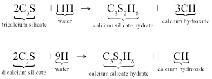
After hydration begins, calcium sulfoaluminate hydrates (ettringite - needle-like structures) rapidly begin to develop. Within a few hours, large prismatic crystals of calcium hydroxide and small fibrous crystals of calcium silicate hydrates will appear and begin to fill the space between the water and cement. Eventually, the ettringite crystals may decompose into monosulfate hydrates. The calcium silicate hydrates' (CSH) structure ranges from poorly crystalline to amorphous, occupies 50-60% of the solid volume of the hydrated cement paste, and has a huge surface area (100-700 m2/g). The CSHs derive their strength from covalent and ionic bonding (~65%), as well as van der Waals bonding (~35%) within the complex structure.
From a materials standpoint, the factors that most affect concrete strength are as follows:
- Mix proportions The lower the water-to-cement (w/c) ratio by mass, the higher the compressive strength (f'c), tensile strength (ft), and Young's modulus (E). Other factors, such as the ratio of cement to aggregate, gradation, surface texture, shape, and stiffness of aggregates, demonstrate a secondary influence.
- Type of cement The rate of the hydration process is highly dependent on the fineness of the cement particles. If a high early strength is desired, it is common to use Type 3 cement, which is just normal cement (Type 1) that has been ground to a much higher fineness.
- Curing Another factor that affects strength significantly is the temperature and humidity at which the concrete is cured. In general, the higher the temperature and humidity, the quicker the hydration. For example, it is common to cure pre-stressed concrete members at temperatures around 140°F with steam in order to obtain 70% or higher of the specified strength within one day of casting.
- Uniformity and consolidation These characteristics refer to the homogeneity of the mix and how well it was initially compacted. The absence of weak zones or large air voids (poor consolidation) and the presence of a concrete with uniform properties should obviously increase the strength, with all other variables remaining the same.
From a testing standpoint, the factors that most affect concrete strength are as follows:
- Moisture condition The wetter the specimen, the higher the strength.
- Roughness of the loading surface The rougher the surface, the higher the strength.
- Rate of loading The faster the loading, the greater the strength.
- Curing temperature and humidity The higher the temperature and humidity at which the specimens were stored before testing, the higher the strength.
- End restraint The type of loading head influences the distribution of stresses across the test specimen. The ideal test loading head is a "brush platten", however, this type of loading head is expensive to manufacture, and repeatability is a problem. Steel heads are typically used, but their rigidity leads to apparent higher strengths. The use of capping compounds to distribute the stresses more evenly across the specimen has ameliorated much of this problem.
- Type of testing machine Testing machines can be classified as hard (very rigid) or soft (less rigid) in terms of their stiffness. A soft machine follows the stress-strain curve better as the specimen fails; however, the additional stored energy will be released and lead to faster crack propagation, and thus a lower apparent strength.
- Geometry of the specimen In the United States, cylinders (traditionally 6" diameter by 12" high, but more recently 4" x 8" ones) are commonly used. In Europe, cubes (6" by 6" or smaller) are used. Although the ratio of cube strength to cylinder strength decreases as the concrete strength increases, it is often assumed that the strength of a cube specimen will be about 1.25 greater than that of a cylinder. In cylinder tests, the length over diameter ratio (1/d) also influences the measured strength. The standard cylinder has a l/d ratio of 2.00, and correction factors can be found for other ratios.
Compression tests are run on a hydraulic testing machine. This machine is different from the universal testing machine that we have been using in other laboratories, as it is powered by a simple, hydraulic pump. This testing machine works only in compression and has a relatively short stroke. For the compression test, the load capacity has to be very high (300,000 lbs or 300 kips or more) in order to test high strength concretes, as the 12 in. cylinders have an area of 28.2 in.2, and concrete strengths can range up to 20 ksi in practical applications. This type of concrete will require a machine with a capacity of at least 600 kips.
The test for Young's modulus and Poisson's ratio is carried out utilizing a compressometer. This device is installed in a concrete cylinder during a compression test and is used to measure both longitudinal and hoop deformations. The longitudinal dial gage is used to compute the longitudinal strains, which in combination with the stress are used to compute Young's modulus. The ratio of the hoop stress to the longitudinal stress can be used to back calculate Poisson's ratio. Both Young's modulus and Poisson's ratio are valid at only low levels of load (certainly less than 40% of ultimate), as microcracking of the concrete will begin at around 30% of the ultimate, and the behavior of the concrete will be clearly non-linear beginning around 60% of the ultimate. After this point, Poisson's ratio loses meaning, as the concrete will begin to exhibit dilatational behavior due to crack growth (i.e., Poisson's ratio will become negative).
While cylinder tests are useful to determine the quality of the concrete delivered to the site, this test does not tell us what the concrete strength in situ is. Even curing cylinders on site does not provide very reliable results. As a result, there has been a great effort to develop economical non-destructive testing (NDT) techniques to assess in-situ concrete strength over the last 40 years. Two of the more common early techniques are using the Schmidt hammer and the Windsor probe. Both of these techniques are examples of surface hardness testing, which can be related to strength through proper calibration procedures.
The Schmidt hammer is a simple, spring-actuated device that shoots a steel weight at a surface and measures its rebound. With suitable calibration of the device to a particular mix, reliable results can be obtained. As it only takes a few seconds to run, this test is a very efficient way of measuring the consistency of the concrete across one or more casting sequences.
The Windsor probe, on the other hand, is a powder-actuated gun that shoots three probes into the concrete in a triangular pattern and measures the average penetration. As with the Schmidt hammer, calibration to a particular mix is important in order to obtain reliable results. The Windsor probe is not exactly non-destructive, as the probes need to be removed, and the surface concrete patched. The depth and extent of these patches is small, so the repair is not a major issue. There are numerous newer and more sophisticated devices and techniques in use today to characterize in-situ concrete strength, but those methods are beyond the scope of this laboratory.
Procedura
Compression Test
- Remove the concrete cylinders from the storage area or curing room, and surface dry the cylinders.
- Select six cylinders for this test, and measure the diameter of each of the cylinders.
- Ensure that the ends of the cylinders are as level as possible. As the top of the cylinders are probably not very flat, one must (a) grind the concrete cylinder ends with a mason's rubbing stone to remove surface irregularities and cast an asphaltic cap at both ends of the cylinder, or (b) place a neoprene end cap on each end. In this lab, we will use neoprene end caps, as this method is by far the simplest. However, even using this technique, major surface imperfections must be removed beforehand.
- Apply the compressive load slowly and continuously until the maximum load is reached. The loading rate should be between 20 psi to 50 psi per second (150 lb. to 300 lb. per second). Failure of the cylinder is imminent during the test when the load indicator slows down and finally stops. Allow the compressive load to continue until the cylinder is crushed. Closely examine the type of failure of the cylinder.
- Record the maximum load and determine the compressive strength for each specimen tested.
Determining Young's Modulus
- For one of the cylinder compression tests, install a compressometer around the cylinder following steps 2.2 to 2.10.
- Unscrew the seven contact screws (2 on the upper lock ring, 3 on the lower lock ring and 2 on the middle ring) until the points are flush with the inside surface of the rings.
- Place the compressometer over the concrete specimen locating the specimen at the center of the ring.
- Place three equal length blocks under the lower ring. The length of the blocks (cylinders) should be vertical to provide the correct height.
- Hand-tighten the 3 contact screws in the lower lock ring and the 2 contact screws in the upper ring against the specimen.
- Hand-tighten the 2 contact screws in the middle ring making sure that the vertical stem of the axial strain dial indicator is midway between the two portions of the middle ring.
- Remove the two-spacer rods.
- Remove the three metal blocks from under the lower ring.
- Zero the axial strain dial indicator with the stem close to the fully extended position.
- Zero the diametrical strain dial indicator with its stem close to the fully pushed-in position.
- Apply a series of loads in steps of about 10,000 lbs., up to about 60,000 lbs. At each load step, record the longitudinal and hoop deformations.
Schmidt Hammer Demonstration
- Mark a 2 ft. x 2 ft. grid on a concrete floor slab, covering an area of 10 ft. x 10 ft. Select a concrete surface that is smooth, dry, and at least 4 inches (or 102 mm) thick.
- At each grid point, conduct and record a Schmidt rebound hammer test, as given in Steps 3.3 to 3.4.
- Before the hammer can be used for testing, the piston must be released out of the hammer into the testing position. If the piston is not extended, place the end of the piston against a stiff surface and gently press the Schmidt hammer firmly against the surface. You will hear a click, and the piston will extend into the test position.
- Gently press the Rebound Hammer against the concrete surface to be tested. When the piston is pressed all the way into the Rebound Hammer, continue to push harder until you hear a rattling sound. Keep the Rebound Hammer firmly pressed against the concrete surface and read the rebound number on the scale.
- Compute the average and standard deviation for this set of measurements.
Wyniki
The cylinders in compression tended to fail along an inclined plane, at roughly 45 degrees. This feature indicates that the failure was not driven by pure compression (crushing of the cylinder) but rather by shear forces, or more precisely by splitting tension stresses.
The compressive test results are computed by dividing the maximum measured load (Pmax) by the measured area. The compressive strength value is taken as the average of three cylinder tests, provided that none of them resulted in a value of less than 500 psi from the average.
The Young's modulus and Poisson's ratio are obtained from the initial slope of the stress-strain curve and the ratio of longitudinal to transverse strains. The value of Young's modulus is often taken as 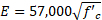 , while Poisson's ratio varies between 0.12 and 0.2.
The average of the Schmidt hammer readings was 32.4 with a standard deviation of 1.3. These results are considered acceptable, and the concrete in situ strength was determined to be 4650 psi based on calibration to parallel laboratory cylinder tests.
Wniosek i Podsumowanie
Compression tests on concrete cylinders were performed, as well as measurements of Young's modulus, Poisson's ratio, and a demonstration of NDT measurements in concrete. Compression test results from the cylinder tests, like those carried out in this laboratory exercise, are relatively simple to conduct and produce results with acceptable variability. Measurements of Poisson's ratio and Young's modulus are difficult to make, and these properties are often calculated by empirical formulae from the compression strength rather than by experimental methodology.
Compression tests of the type described herein are used to monitor the strength gain in concrete structures. The results at 28 days have to meet discrete specifications, but in general, the test is not run with only the specific purpose of meeting specifications, or checking the strength of a particular member. The main idea of these tests is to monitor the quality of all of the concrete delivered over the lifespan of the entire project.
Another common application of cylinder testing is to test cores extracted from existing structures. In these cases, the intent is to determine if the structure can carry loads higher than initially designed for. One example is in older bridges, where the increased truck loads require that bridges be rated for new load combinations (weight per axle and axle spacing, for example) or in forensic investigations where after a failure has occurred, it is necessary to rule out certain failure modes.
Tagi
Przejdź do...
Filmy z tej kolekcji:

Now Playing
Compression Tests on Hardened Concrete
Structural Engineering
15.2K Wyświetleń

Material Constants
Structural Engineering
23.4K Wyświetleń

Stress-Strain Characteristics of Steels
Structural Engineering
109.3K Wyświetleń

Stress-Strain Characteristics of Aluminum
Structural Engineering
88.4K Wyświetleń

Charpy Impact Test of Cold Formed and Hot Rolled Steels Under Diverse Temperature Conditions
Structural Engineering
32.1K Wyświetleń

Rockwell Hardness Test and the Effect of Treatment on Steel
Structural Engineering
28.3K Wyświetleń

Buckling of Steel Columns
Structural Engineering
36.1K Wyświetleń

Dynamics of Structures
Structural Engineering
11.5K Wyświetleń

Fatigue of Metals
Structural Engineering
40.5K Wyświetleń

Tension Tests of Polymers
Structural Engineering
25.3K Wyświetleń

Tension Test of Fiber-Reinforced Polymeric Materials
Structural Engineering
14.4K Wyświetleń

Aggregates for Concrete and Asphaltic Mixes
Structural Engineering
12.1K Wyświetleń

Tests on Fresh Concrete
Structural Engineering
25.7K Wyświetleń

Tests of Hardened Concrete in Tension
Structural Engineering
23.5K Wyświetleń

Tests on Wood
Structural Engineering
32.9K Wyświetleń
Copyright © 2025 MyJoVE Corporation. Wszelkie prawa zastrzeżone