
Testing the Heat Transfer Efficiency of a Finned-tube Heat Exchanger
Overview
Source: Michael G. Benton and Kerry M. Dooley, Department of Chemical Engineering, Louisiana State University, Baton Rouge, LA
Heat exchangers transfer heat from one fluid to another fluid. Multiple classes of heat exchangers exist to fill different needs. Some of the most common types are shell and tube exchangers and plate exchangers1. Shell and tube heat exchangers use a system of tubes through which fluid flows1. One set of tubes contains the liquid to be cooled or heated, while the second set contains the liquid that will either absorb heat or transmit it1. Plate heat exchangers use a similar concept, in which plates are closely joined together with a small gap between each for liquid to flow1. The fluid flowing between the plates alternates between hot and cold so that heat will move into or out of the necessary streams1. These exchangers have large surface areas, so they are usually more efficient1.
The goal for this experiment is to test the heat transfer efficiency of a finned-tube heat exchanger (Figure 1) and compare it to the theoretical efficiency of a heat exchanger without fins. The experimental data will be measured for three different flow rates of monoethylene glycol (MEG). Two different water flow rates for each MEG flow rate will be used. Using the Wilson plot method the heat transfer coefficients will be determined from the experimental data. Additionally, the Reynold's number and the amount of heat transferred will be compared for flow with and without the fins to evaluate heat transfer efficiency.

Figure 1: Finned-tube Heat Exchanger. 1) MEG outlet temperature 2) water inlet temperature 3) MEG inlet temperature 4) water outlet temperature 5) water meter 6) MEG accumulation sight glass/cylinder.
Principles
Heat exchangers transfer heat between two or more fluids. The exchangers use fluid species which flow in a separate space from an opposing stream that is providing heat. Fins can be added to the flow area to facilitate more heat transfer, as they increase the surface area available for transference. The added fins decrease the area through which the species flows and provide more surfaces on which boundary layers can form, resulting in flow that is less turbulent. The less turbulent a flow, the larger boundary layer it will have. A boundary layer inhibits heat transfer, so with less turbulent flow less heat is transferred. When the boundary layer is laminar, there is very little mixing.
The relationship between the area through which heat can flow and the heat transfer coefficient is used in calculating the total heat transferred. This relationship is calculated through Equation 1:
 (1)
(1)
where Q is heat transferred (Btu/hr), U is overall heat transfer coefficient, A is area through which heat is transferred (ft2), ΔTLM is the logarithmic mean temperature difference.
The overall heat transfer coefficient equation is:
 (2)
(2)
where Ab is the surface area of bare inner pipe, Af is the surface area of the fins, ALM is the logarithmic mean area difference, A is the surface area of the pipe (o = outside, i = inside), Δx thickness of the pipe, k is thermal conductivity of the pipe, h = Individual heat transfer coefficient. (o=outside, i=inside)
The Wilson plot method uses experimental data to find UoAo from typical energy balance on the MEG flow and plot its reciprocal to 1/Re0.8 of the inside pipe. By fitting a straight line and finding the y-intercept, which is related to the heat transfer coefficient and is described in the first two terms on the right of the equation above. A typical longitudinal rectangular profile fin efficiency equation is used as the second equation to solve for the heat transfer coefficient and fin efficiency by minimizing the sum of squares of an objective function. This method is applied to MEG flow conditions with varying water flow rates.
To calculate the heat transfer coefficient, the Reynolds Number is used, which is given by the following equation:
 (3)
(3)
where G is the mass velocity of fluid flow, D is the diameter of pipe where the fluid flows (Deq, the equivalent diameter will replace D for calculations with fins), and µ is the fluid's viscosity. Fin efficiency equation for a longitudinal rectangular profile fin is:
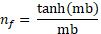 (4)
(4)
where m is √(2h/kt), h is the heat transfer coefficient, k is thermal conductivity of the pipe, t is thickness of fin, and b is the height of fin.
Procedure
1. Start and Flow Rate Determination
- Open the charge valve located below the steam generator.
- Start the unit, and allow 15 min for steam to begin forming.
- Calculate the flow rate of water
- Start a stopwatch and monitor the gauge displaying the volume of water.
- Stop the watch after 30 s and record the total volume of water displayed on the gauge.
- Divide the volume of water by the time to determine the volumetric flow rate.
- Record the MEG flow rate from the flow meter.
- Observe the temperature from the thermocouples, and record the values.
2. Varying the flow rate and shut down
- To collect data for 6 different runs, set the flow rate of water to either a high or low flow rate and run it with a high, medium, or low flow rate of MEG.
- For reference, the previous flow rates have been used: 0.0439, 0.0881, and 0.1323 gal/sec for the low, medium, and high flow rates of MEG, respectively.
- As previous, record the volumetric flow rates and temperature difference on the thermocouple for each run.
- When finished, shut down the instrument.
- Close the valves to stop the flow of steam, monoethylene glycol and water.
- Turn off the main switch.
3. Calculations
- Use Equation 1 to calculate the total heat transferred, Q, with the temperature difference read from the thermocouples (devices used to measure temperature) and the known physical dimensions of the heat exchanger (found in the user manual for the unit being operated). The temperature differences can be taken from the temperature readings of each run.
- Calculate the heat transferred for each unique trial run, and use the Wilson plot method to find the heat transfer coefficients for the three MEG flow rates.
- Compare the calculated heat transferred and Reynolds number to theoretical values of the heat exchanger without fins.
Results
The finned tube heat exchanger did not reach turbulent flow (Figure 2). The fins provide additional surfaces on which boundary layers form, as known through laminar and turbulent flow theory. If the fluid is not at a sufficient velocity, the fluid will not reach turbulence. The boundary layers between the fins overlap in the laminar region, so the fluid will remain laminar.
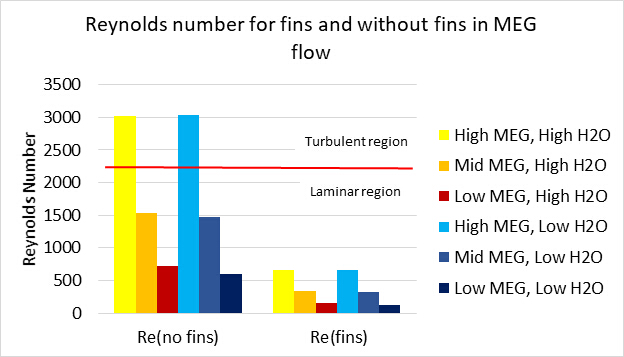
Figure 2: Reynolds numbers for each setting.
The amount of heat transferred, Q, in the tubes with and without fins at different flow rates of MEG was compared (Figure 3). The results show that a finned-tube transfers more heat than a tube without fins at the same operating conditions. In this experiment, the fins clearly improved heat transfer. This is because heat transfer is more effective when there is a greater surface area available. The finned-tube heat exchanger transferred more heat (Figure 3), despite the lower Reynolds number (Figure 2).

Figure 3: Heat transferred between exchangers with and without fins at each flow rate.
Application and Summary
Heat exchangers are used in a variety of industries, including agriculture, chemical production, and HVAC. The goal for this experiment was to test the heat transfer efficiency of a finned-tube heat exchanger and compare it to the theoretical efficiency of a heat exchanger without fins. Experimental data was measured for three different flow rates of monoethylene glycol (MEG) and two unique water flow rates for each MEG flow rate used. The Reynold's number was determined for flow with and without the fins and was used to calculate the heat transfer coefficient, surface area, and fin efficiency for each unique trial run. This data was used to evaluate if turbulent flow is possible without the fins and under which set of trial conditions the most heat transfer occurs. The finned tubes did not reach turbulent flow. The results showed that a fin tube will transfer more heat than a tube without fins at the same operating conditions because the flow of MEG through the heat exchanger will not reach turbulence.
In the agriculture industry, heat exchangers are used in the processing of sugar and ethanol2. Both of these products are processed into a juice, which must be heated to be further processed2. Heat exchangers are used in heating the juices for clarification2. Once the juices have been processed into even syrups, further heating with exchangers is necessary to continue processing and form molasses2. Molasses is cooled using heat exchangers, after which it can be stored for later processing2.
Heating, ventilation, and air conditioning systems, together known as HVAC, all make use of heat exchangers3. Household air conditioning and heating units make use of heat exchangers3. In larger settings, chemical plants, hospitals, and transportation centers all make use of similar heat exchanger HVAC, on a much larger scale3. In the chemical industry, heat exchangers are used for heating and cooling a large variety of processes4. Fermentation, distillation, and fragmentation all make use of heat exchangers4. Even more processes like rectification and purification require heat exchangers4.
References
- Types of Heat Exchangers." Types of Heat Exchangers. N.p., n.d. Web. 19 Jan. 2017.
- Heat exchangers for sugar factories and distilleries." Heat exchanger for sugar and ethanol industry. N.p., n.d. Web. 19 Jan. 2017.
- Biotechnology and green chemistry heat exchangers." Heat exchanger for green chemical industry. N.p., n.d. Web. 19 Jan. 2017.
- Heat exchangers for heating and cooling." Heat exchangers for district heating, cooling and HVAC. N.p., n.d. Web. 19 Jan. 2017.
Skip to...
Videos from this collection:

Now Playing
Testing the Heat Transfer Efficiency of a Finned-tube Heat Exchanger
Chemical Engineering
17.9K Views

Using a Tray Dryer to Investigate Convective and Conductive Heat Transfer
Chemical Engineering
43.9K Views

Viscosity of Propylene Glycol Solutions
Chemical Engineering
32.7K Views

Porosimetry of a Silica Alumina Powder
Chemical Engineering
9.6K Views

Demonstration of the Power Law Model Through Extrusion
Chemical Engineering
10.0K Views

Gas Absorber
Chemical Engineering
36.6K Views

Vapor-liquid Equilibrium
Chemical Engineering
88.7K Views

The Effect of Reflux Ratio on Tray Distillation Efficiency
Chemical Engineering
77.6K Views

Efficiency of Liquid-liquid Extraction
Chemical Engineering
48.4K Views

Liquid Phase Reactor: Sucrose Inversion
Chemical Engineering
9.7K Views

Crystallization of Salicylic Acid via Chemical Modification
Chemical Engineering
24.2K Views

Single and Two-phase Flow in a Packed Bed Reactor
Chemical Engineering
18.9K Views

Kinetics of Addition Polymerization to Polydimethylsiloxane
Chemical Engineering
16.1K Views

Catalytic Reactor: Hydrogenation of Ethylene
Chemical Engineering
30.4K Views

Evaluating the Heat Transfer of a Spin-and-Chill
Chemical Engineering
7.4K Views
Copyright © 2025 MyJoVE Corporation. All rights reserved