
Gas Absorber
Overview
Source: Michael G. Benton and Kerry M. Dooley, Department of Chemical Engineering, Louisiana State University, Baton Rouge, LA
Gas absorbers are used to remove contaminants from gas streams. Multiple designs are used to accomplish this objective1. A packed bed column uses gas and liquid streams running counter to each other in a column packed with loose packing materials, such as ceramics, metals, and plastics, or structured packing1. The packed bed uses surface area created by the packing to create a maximum amount of efficient contact between the two phases1. The systems are low maintenance and can handle corrosive materials with high mass transfer rates1. Spray columns are another type of absorber, which uses constant direct contact between the two phases, with gas moving up and liquid being sprayed down into the gas flow1. This system only has one stage and poor mass transfer rates, but is very effective for solutes with high liquid solubility1.
The goal of this experiment is to determine how variables including gas flow rate, water flow rate, and carbon dioxide concentration affect the overall mass transfer coefficient in a gas absorber. Understanding how these parameters affect CO2 removal enables contaminant removal to be optimized. The experiment uses a randomly packed water counter-flow gas absorption column. Eight runs with two different gas flow rates, liquid flow rates, and CO2 concentrations were used. During each run, the partial pressures were taken from the bottom, middle, and top of the column unit, and the equilibrium partial pressures were calculated. These pressures were then used to find the mass transfer coefficient, and the mass transfer coefficients were compared to theoretical values.
Principles
A gas absorption unit (Figure 1) uses contact with a liquid to remove a substance from a gas mixture. Mass is transferred from the gas mixture to the liquid via absorption.
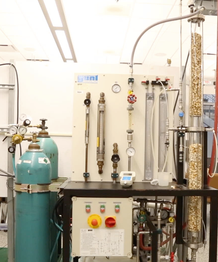
Figure 1: Typical gas absorption column.
The overall mass transfer coefficient is the rate at which the concentration of one species moves from one fluid to the other (Equation 1).
 (1)
(1)
In equation 1, Gs is the gas molar flow rate per cross-sectional area of the column, pAg is the partial pressure of CO2, p*A is the pressure in equilibrium with pAg, a is the interfacial area/volume or “effective area” (a function of column packing), z is the height of the packing, and KG is the overall mass transfer coefficient in mols/(pressure x interfacial area x time). Mass transfer depends on the mass transfer coefficients in each phase and the amount of interfacial area available in the absorber. Henry's Law or Raoult's Law is applied to approximate the partial pressures. They are two laws that describe the partial pressure of a component in a mixture, and are used together in order to fully describe the behavior of the mixture at the limits of the vapor-liquid equilibrium relationship. The objective of a gas absorption column is to control the effluent partial pressure of contaminant. A liquid solvent flows counter-current to the gas stream to remove the contaminant through convective mass transfer. The overall mass transfer of a water counter-flow packed column is measured in this study to determine the effects of water flow, gas flow, and CO2 gas concentration. The coefficients will then be compared to theoretical values.
Procedure
The experiment uses a randomly packed water counter-flow gas absorption column. The column is packed with 34 cm of 13 mm berl saddles with 465 m2/m3 surface (effective) area. The pressure entering the system is about 1.42 bar with a temperature of about 26 °C, and valves at the entrance and exit of the column allow gas to escape. An "Oxy Baby" Infra-red spectrometer, directly connected to the unit at various locations, measures gas composition, and tanks of pure gas are used for calibration.
1. Operating the Gas Absorber
- Turn on the master switch and close the adjusting valve used to control the amount of water in the column
- Open the air flow valve completely and the adjusting valve for column pressure.
- Set the air flow rate to the desired level (use a minimum of 20 L/min and increase as needed), and set the column pressure to ~ 1.4 bar and 25°C using the adjusting valve for pressure.
- Start the carbon dioxide flow rate at ~ 4 L/min.
- Set the water flow at ~ 75 L/h, and adjust the water level to maintain a constant height. Tweak if necessary while running to ensure constant height.
- Sample the CO2 partial pressure at the base, center and head of the column using the pressure taps and the infra-red spectrometer.
- Perform eight different runs, using two different gas flow rates, liquid flow rates, and CO2 concentrations. This will enable determination of the most important variables.
- Allow the system to achieve steady-state when any flow rate is altered. This typically takes 30 - 45 min.
Results
Partial pressures were taken from each trial run. Mass transfer coefficients were calculated from these and compared to predicted values (Figure 2). The predicted values arise from the calculated operating line for the absorber (see reference 2 for an in-depth discussion of the operating line). Solid lines represent the values calculated using the operating line, while triangles represent the experimental mass transfer coefficient values. Confidence intervals for the model values and the mean mass transfer coefficient were plotted with dashed lines. These values were compared to determine how the experimental parameters (liquid flow rate, gas flow rate, and CO2 partial pressure) affected the overall mass transfer coefficient. Under these operating conditions, only liquid flow rate had a statistically significant effect on mass transfer when compared to the confidence interval. The results showed that gas flow rate and feed composition had little to no effect on the mass transfer coefficient.
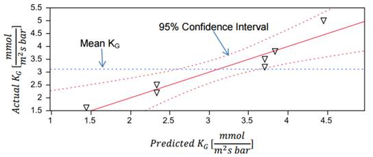
Figure 2: Model of the predicted and actual values of the mass transfer coefficient.
Theoretical KG values for a high (30 L/min) and low (20 L/min) were calculated from mass transfer coefficient correlations and are shown as blue and green lines, respectively, in Figure 3. The experimental KG values at a variety of liquid flow rates were plotted against the theoretical values and showed similar trends, verifying the dependence of KG on liquid flow rate. The theoretical values showed some variation from the experimental values, attributable to minor experimental error.

Figure 3: A graphical depiction of experimental value compared to theoretical values.
Application and Summary
The goal of this experiment was to use factors of gas flow rate, water flow rate, and carbon dioxide concentration to determine the overall mass transfer coefficient in a gas absorber. The experiment used a randomly packed GUNT CE 400 water counter-flow gas absorption column. Eight runs with two different gas flow rates, liquid flow rates, and CO2 concentrations were performed. Partial pressures were taken from the bottom, middle, and top of the column unit, and these pressures were then used to find the mass transfer coefficient.
Under these operating conditions, only the liquid flow rate had a significant statistical effect on mass transfer when compared to the confidence interval for the given conditions. The process is liquid-phase mass transfer controlled. Gas-related factors such as CO2 concentration and gas flow rate will have little to no significance.
Gas absorption is an important mechanism for safety in the production of chlorine3. During normal operation, gas absorbers treat any consistently occurring leaks. The start-up of a chlorine operation must be treated until it produces a gas-free product. In the event of a breakdown in the process, absorbers must be used to treat the gas that has been produced. Additionally, when new leaks form, the main emergency response unit is the standby gas absorbers. Treatment units are vitally important in these operating conditions, as they help create a safe environment when dealing with a dangerous product3.
When refining natural gas, absorption towers are used to remove natural gas liquids from the gas phase4. An absorbing oil with an affinity to natural gas liquids removes the liquid from the gas phase, purifying the product. The oil with natural gas liquids is then further purified to recover the liquids, such as butane, pentanes and other molecules. The oil can then be used again for treatment.
Absorption is also used to remove the major impurities CO2 and H2S from wellhead natural gas, converting it to pipeline gas. The process uses aqueous amines or glycols as solvents at low temperatures (typically <40 °C)5.
References
- Absorbers - Separations: Chemical - MEL Equipment Encyclopedia 4.0. N.p., n.d. Web. 28 Jan. 2017.
- Welty, James R., Rorrer, Gregory L., and David G. Foster. Fundamentals of Momentum, Heat, and Mass Transfer. 6th ed. John Wiley & Sons, Inc., Hoboken, NJ, 2015
- Chloric Gas Absorption." GEA engineering for a better world. N.p., n.d. Web. 28 Jan. 2017.
- NaturalGas.org." NaturalGasorg. N.p., n.d. Web. 28 Jan. 2017.
- Fundamentals of Natural Gas Processing, A.J. Kidnay and W.R. Parrish, Taylor and Francis, Boca Raton, 2006.
Tags
Skip to...
Videos from this collection:

Now Playing
Gas Absorber
Chemical Engineering
36.7K Views

Testing the Heat Transfer Efficiency of a Finned-tube Heat Exchanger
Chemical Engineering
17.9K Views

Using a Tray Dryer to Investigate Convective and Conductive Heat Transfer
Chemical Engineering
43.9K Views

Viscosity of Propylene Glycol Solutions
Chemical Engineering
32.8K Views

Porosimetry of a Silica Alumina Powder
Chemical Engineering
9.6K Views

Demonstration of the Power Law Model Through Extrusion
Chemical Engineering
10.0K Views

Vapor-liquid Equilibrium
Chemical Engineering
88.9K Views

The Effect of Reflux Ratio on Tray Distillation Efficiency
Chemical Engineering
77.7K Views

Efficiency of Liquid-liquid Extraction
Chemical Engineering
48.5K Views

Liquid Phase Reactor: Sucrose Inversion
Chemical Engineering
9.7K Views

Crystallization of Salicylic Acid via Chemical Modification
Chemical Engineering
24.2K Views

Single and Two-phase Flow in a Packed Bed Reactor
Chemical Engineering
18.9K Views

Kinetics of Addition Polymerization to Polydimethylsiloxane
Chemical Engineering
16.1K Views

Catalytic Reactor: Hydrogenation of Ethylene
Chemical Engineering
30.4K Views

Evaluating the Heat Transfer of a Spin-and-Chill
Chemical Engineering
7.4K Views
Copyright © 2025 MyJoVE Corporation. All rights reserved