
Tension Test of Fiber-Reinforced Polymeric Materials
Przegląd
Source: Roberto Leon, Department of Civil and Environmental Engineering, Virginia Tech, Blacksburg, VA
Fiber-reinforced polymeric materials (FRP) are composite materials that are formed by longitudinal fibers embedded in a polymeric resin, thereby creating a polymer matrix with aligned fibers along one or more directions. In its simplest form, the fibers in FRP materials are aligned in an orderly, parallel fashion, thus imparting orthotropic material characteristics, meaning that the material will behave differently in the two directions. Parallel to the fibers, the material will be very strong and/or stiff, whereas perpendicular to the fibers will be very weak, as the strength can only be attributed to the resin instead of the whole matrix.
An example of this unidirectional configuration is the commercially available FRP reinforcing bars, which mimic the conventional steel bars used in reinforced concrete construction. FRP materials are used both as stand-alone structures such as pedestrian bridges and staircases, and also as materials to strengthen and repair existing structures. The thin, long plates are often epoxied to existing concrete structures to add strength. In this case, the FRP bars act as external reinforcement. The FRP bars and plates are lighter and more corrosion resistant, so they are finding applications in bridge decks and parking garages, where de-icing slats lead to rapid deterioration of conventional bars.
In this laboratory exercise, the tensile behavior of a unidirectional specimen will be studied, with emphasis on its ultimate strength and deformation capacity. The behavior of the specimen is expected to be elastic until failure, which is expected to occur in a sudden and explosive manner. This behavior should be contrasted with those of ductile steels, which exhibit extensive deformation capacity and strain hardening before failure.
Zasady
The strength of the FRP material is directly related to the strength of the individual fibers and the amount of fibers that can be put into a unit volume. Theoretically, one can achieve as high as 90% fibers by volume; however, this high a density of fibers cannot be achieved through economically viable commercial fabrication processes. Typically, most FRP material applications in civil engineering have around 50-60% fibers by volume.
There are several types of FRP materials based on different classes of fibers, such as glass fiber-reinforced polymers (GFRP), carbon fiber-reinforced polymers (CFRP), and aramid fiber-reinforced polymers (AFRP). Aramids are a class of synthetic polymers, similar to nylon, that exhibit extraordinary strength and resistance to temperature change. Table 1 shows the variety of different characteristics of each class of fibers. Care must be exercised when evaluating the suitability of FRP materials for a particular application in order to match base material and FRP properties, such as ensuring complementary thermal coefficients of expansion to ensure proper long-term behavior. In addition, one must confirm that there is a lack of chemical interaction between the FRP and base material, as many fibers and resins are sensitive to corrosion, moisture, and high temperature in both fabrication and use.
| Characteristic | Glass Fibers | Carbon Fibers | Aramid Fibers |
| Strength | High | Very high | High |
| Stiffness | Low | Very high | |
| Thermally Stable | <1500ºF | <3500ºF | ± 350ºF |
| Impact Resistance | Low | Low | High |
| Moisture Resistance | Sensitive | Highly Resistant | Sensitive |
| Chemical Resistance | Sensitive | Highly Resistant | Highly Resistant |
| Conductivity | Highly insulating | High conductivity | Low conductivity |
| Price | $ | $$$ | $$ |
Table 1. FRP material properties.
Beyond the simplest uniaxial application in rebars, there are many applications that utilize stacks of uniaxial fibers in either specific or random directions to create laminate materials.
In most cases, these plates are still orthotropic, but now with two strong directions and one weak direction (out of the plane). In the assembly of these structures, there are three important definitions to consider. A ply is a single layer of fiber mat or single pre-preg sheet. A pre-preg sheet is a fiber mat impregnated with resin, pre-cured under heat, pressure, or both, and intended for field applications where, for example, the sheet will be glued to an existing surface to strengthen it. A laminate is a cured stack of several plies. Notice that a laminate can be made up of plies with different fibers or fiber volumes, leading to easy customization of the FRP for its intended use. Laminates are used where the FRP can be applied to a smooth surface and only partial coverage is needed; plies and pre-preg sheets are used when wrapping entire structural elements and where the surface is uneven.
When creating laminates, pressure needs to be applied to squeeze out as much resin as possible in order to increase the fiber volume. Some common resins used in FRP materials include epoxies, vinylesters, and polyesters. The principal function of resins is to transfer stress between adjoining fibers in the matrix and to protect the fibers from both mechanical and environmental damage. Polymer resins are generally petrochemical or natural gas derivatives and can either be thermosets or thermoplastics. While thermosets cannot be deformed upon curing, thermoplastics, such as polyesters and vinyl esters, are deformed and crosslinked upon curing, thereby imparting greater thermal resistance. Both types of polymers can be used in composite materials and can benefit in combination with reinforcing fibers. However, the majority of thermoplastic polymers are not used in composite form, as they already exhibit high strength, whereas thermosetting polymers generally require high fiber volumes of strong fibers in order to achieve the same strength. Thermosets are the dominant polymer in the current composite industry, as the wide variety of polymers available can satisfy virtually every conceivable end use application. The polymer resins are selected and tailored for each individual application, strongly based on the physical and mechanical properties of the product and the fabrication process requirements.
In addition to the reinforcing fibers and resins, there are also fillers and additives that play an important role in the composite system. Fillers and additives are processing aides that impart "special" properties to tailor the end product to the desired specification. Fillers or extenders are used in many composites material systems and have three primary functions:
- To improve certain mechanical properties, such as compressive strength, fire resistance, crack propagation, and chemical resistance.
- To improve processability of the composites system, such as uniformity of physical features and surface finish.
- To reduce material cost by replacing some of the more expensive polymer and reinforcement in the system.
Some common fillers include calcium carbonate, clay, talc, silica, mica, and microspheres; however, the most common filler is calcium carbonate because of its low cost and availability.
On the other hand, additives cover a wide variety of different materials that are used in relatively small quantities, but nevertheless play an integral role in the processing and end product performance of the composite. Additives play a myriad of roles, such as:
- To modify the cure rate.
- To extend shelf life and prevent shrinkage.
- To improve weatherability and reduce viscosity.
- To add color and reduce porosity.
Some common additives include catalysts and promoters, used to affect the cure of thermoset polymers, inhibitors, to control the thermoset reaction, release agents, to allow parts to be more easily removed from their mold, as well as pigments, UV absorbers, and fire retardants.
When considering the entire FRP material system (fibers, resin, fillers, and additives), the principal factors affecting the mechanical properties of FRP are the type of fiber reinforcement, fiber volume, fiber orientation, resin type, manufacturing process, and quality control.
For the three main classes of fibers used in FRPs - carbon, aramid and glass- the stress-strain behavior to failure is essentially linearly elastic, and the fibers have very low strain capacity. This characteristic results in sudden failures, without any evidence of ductility.
When modeling fiber and matrix behavior, either the strain capacity of the resin or the fiber can govern the mechanical behavior. In practice, the material will be very heterogeneous at the small scale between the fiber and matrix; however, for modeling and design purposes, we consider it homogeneous with an equivalent modulus of elasticity based upon the rule of mixtures. The rule of mixtures dictates that the various properties of composite materials will be the result of the weighted mean from the constituent parts, either in parallel or in series. Before the cracking of fiber in FRP materials or before the cracking of matrix in FRC, the composite material will behave according to the rule of mixtures:
σc = σmVm + ΣηfiσfiVfi
Vm + ΣVfi = 1
σc = strength of the composite
Vm = volume fraction of the fibers
σm = strength of the matrix
Vm = volume fraction of the matrix
σfi = strength of the fibers
where,
Nf = 0.375, for random fibers
Nf = 1, for unidirectional fiber stressed in fiber direction
Nf = 0, for unidirectional fiber stressed perpendicular to the fiber direction
A similar equation can be used for calculating the modulus of elasticity (Ec) of a composite. Consider a woven hybrid composite fabric composed of aramid fibers (sf1 = 500,000 psi, Ef1 = 50x106 psi) and carbon fibers (sf2 = 300,000 psi and, Ef2 = 15x106 psi) in an epoxy matrix (sm = 8,000 psi and Em = 0.50x10⁶ psi). In this fabric, the carbon fibers run in the 0o direction, and the aramid fibers run in the 90o direction. The total fiber volume fraction is 0.60, with an equal volume of carbon and aramid fiber. The strengths and modulus in the two perpendicular directions are:
sc,0° = sm Vm + S hfisfi Vfi = (8)(0.4)+(300)(0.6) = 183.2 ksi = s1
sc,90° = sm Vm + S hfisfi Vfi = (8)(0.4)+(500)(0.6) = 303.2 ksi = s2
Ec,0° = Em Vm + S hfiEfi Vfi = (0.5)(0.4) + (50)(0.6)= 30.2 x 10⁶ ksi = E1
Ec,90° = Em Vm + S hfiEfi Vfi = (0.5)(0.4) + (15)(0.6)= 9.2 x 10⁶ ksi = E2
Additionally, when designing FRP materials, the fibers must be long enough to break, but not pull out of the material. For most common applications, fibers are more than long enough, but nonetheless must be considered a design requisite.
To demonstrate and contrast the stress-strain behavior of two types of FRP, a relatively weak glass FRP and a strong carbon FRP, simple tension tests will be conducted as described next. An important issue in testing these materials is that the soft matrix can be easily damaged by the hard metal grips, leading to failures just outside the grips. Tests that fail in this manner are generally not considered to produce valid results. A simple procedure that has given satisfactory results is described below.
Procedura
- Take proper safety precautions, and wear eye protection because the explosive failure typical of these specimens sends many small, sharp shards flying.
- Obtain four FRP specimens. Two will be from a unidirectional 0.5-inch E-glass FRP plate cut into 1" x 8" specimens, one along the direction of the fibers and one perpendicular to the fibers. The third specimens will be a 0.25-inch carbon FRP rebar, and the fourth will be a 0.25 FRP E-glass rebar. The rebar specimens should be about 24 inches long.
- Attach holders for the instrument by embedding 12 in. of the ends of the specimens into slightly larger steel round and rectangular sections and infill the empty spaces with high-strength epoxy. Let the epoxy cure as per manufacture's specifications. This type of end connection is needed because the serrations in conventional UTM grips will destroy the resin and lead to premature end failures.
- Proceed in the same manner as the other tension tests by turning on the UTM and initializing its software.
- Insert the specimens into the grips and tighten them.
- Load the specimens in deflection control at a rate of about 0.2 in. per minute.
- If an extensometer is used to measure Young's modulus, make sure to demount it at a strain of 0.01.
- As the specimen begins to fail, popping sounds and small shards will begin to fall off the specimen, followed by an explosive failure of the material, which separates into a fibrous flower-like structure.
Wyniki
Typical stress-strain curves for the E-glass FRP plate specimens are shown for the plate with the two uniaxial layers aligned longitudinally (Fig. 1) and respectively perpendicularly (Fig. 2) to the direction of loading. For the case of the load applied parallel to the fibers (Fig. 1), the maximum force was 12.32 kips, corresponding to a tensile strength of 98.6 ksi. The failure occurred at a strain of 2.98% and the modulus of elasticity, calculated from a line tangent at 30% of the ultimate load, was 5686 ksi. Since an extensometer was not used, this value should be taken only as indicative of the Young's modulus. The behavior is essentially linear to failure. The results are reasonable for a material specified at 50% E-glass fiber volume.

Figure 1: Stress-strain curves for the E-glass FRP plate: load applied parallel with the fibers.
For the case of the load applied perpendicular to the fibers (Fig. 2), the maximum force was 2.72 kips, corresponding to a tensile strength of 10.9 ksi. The failure occurred at a strain of 2.24 and the modulus of elasticity, calculated from a line tangent at 30% of the ultimate load, was 640 ksi.
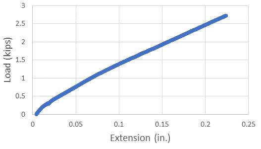
Figure 2: Stress-strain curves for the E-glass FRP plate: load applied perpendicular to the fibers.
As expected, there was a very large difference between the two directions as shown in the comparison graph (Fig. 3). This emphasizes the tailorability of the material properties; in this case we have a material that is strong in one direction and weak in the other.
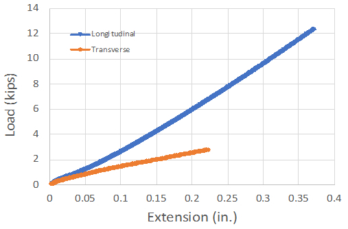
Figure 3: Stress-strain curves for the E-glass FRP plate: load applied parallel (blue) and respectively, perpendicular (orange) to the fibers.
The failure surfaces bear witness to this, with the one for the fibers aligned longitudinally showing numerous broken fibers and the one with the fibers aligned perpendicularly showing the typical surface for a resin failure at an interface.
The plot in Fig. 4 shows a comparison of the behavior of the FRP rebars. There is a very significant drop in strength (a factor of about 2) and modulus of elasticity (about a factor of 4) decrease when we compare the carbon FRP and the E-glass FRP curves. All of these FRP materials can be seen to have very little or no ductility, failing immediately after carrying their maximum load.

Figure 4: Linearized stress-strain curves for E-glass (orange) and respectively, carbon (blue) FRP rebars.
Wniosek i Podsumowanie
FRP materials are light, strong composites used extensively in both civil, mechanical, and aerospace applications. They are made up of strong fibers embedded in a resin or similar matrix, and they are manufactured in many forms, including prepeg strips and laminates. Their strength and stiffness can be tailored by varying the amounts, types, and directionality of the fibers. FRP materials have a much smaller deformation capacity than metals or polymers and give little warning of failure, thus are important to study the manner and mechanics of failure.
FRP materials are used in a myriad of civil engineering applications from transportation to construction materials, marine to electronic applications, and even consumer products to business equipment. There are GFRP poles and towers for hanging power and telephone lines, FRP stairwells and parking garages, FRP roofing, seawall reinforcement, FRP marine fenders, and ground anchorage to name a few. They are also extensively used to strengthen and repair structures.
Many highway structures, such as the Prodeck Bridge System and Auto Skyway, employ FRP materials to help reinforce and support the loads that traverse the bridge in the road systems. Even the guardrails that one sees on the sides of the highways can be built using FRP materials. FRP materials are also used to transport people over pedestrian bridges, such as the Aber Feldy Golf Club Bridge in Scotland and the Shank Castle footbridge in Cumbria, U.K.
Many marine applications use FRP materials for their resistance to corrosion and salt. FRP is used extensively in the boating industry, as well as for naval structures and pipelines. FRP materials are not only seen in practical construction applications, but also in fun applications, such as in artistic architectural forms and roller coasters. The shooting arrow sculpture in San Francisco, named "Cupid's Span", is made from FRP materials, as are the pedestals in many roller coasters in Six Flags nationwide.
Przejdź do...
Filmy z tej kolekcji:

Now Playing
Tension Test of Fiber-Reinforced Polymeric Materials
Structural Engineering
14.4K Wyświetleń

Material Constants
Structural Engineering
23.5K Wyświetleń

Stress-Strain Characteristics of Steels
Structural Engineering
109.5K Wyświetleń

Stress-Strain Characteristics of Aluminum
Structural Engineering
88.6K Wyświetleń

Charpy Impact Test of Cold Formed and Hot Rolled Steels Under Diverse Temperature Conditions
Structural Engineering
32.2K Wyświetleń

Rockwell Hardness Test and the Effect of Treatment on Steel
Structural Engineering
28.3K Wyświetleń

Buckling of Steel Columns
Structural Engineering
36.1K Wyświetleń

Dynamics of Structures
Structural Engineering
11.5K Wyświetleń

Fatigue of Metals
Structural Engineering
40.7K Wyświetleń

Tension Tests of Polymers
Structural Engineering
25.4K Wyświetleń

Aggregates for Concrete and Asphaltic Mixes
Structural Engineering
12.1K Wyświetleń

Tests on Fresh Concrete
Structural Engineering
25.8K Wyświetleń

Compression Tests on Hardened Concrete
Structural Engineering
15.2K Wyświetleń

Tests of Hardened Concrete in Tension
Structural Engineering
23.5K Wyświetleń

Tests on Wood
Structural Engineering
32.9K Wyświetleń
Copyright © 2025 MyJoVE Corporation. Wszelkie prawa zastrzeżone