AC Induction Motor Characterization
Genel Bakış
Source: Ali Bazzi, Department of Electrical Engineering, University of Connecticut, Storrs, CT.
The objectives of this experiment are to find the equivalent circuit parameters of a three-phase induction motor using the per-phase equivalent circuit and tests similar to those used in transformer characterization. In electrical engineering, an equivalent circuit (or theoretical circuit) can be determined for a given system. The equivalent circuit retains all characteristics of the original system, and is used as a model to simplify calculations. Another objective is to operate the motor in the linear torque-speed region.
İlkeler
The three-phase induction motor is fed by three-phase voltages or currents that induce three magnetic fields. These fields add up to a cumulative magnetic field, which rotates in space at constant amplitude and is termed the stator magnetic field. The magnetic field induces current in metal rotor bars or coils, which in turn induce their own magnetic field, termed the rotor magnetic field. The rotor hangs inside the stator, and the rotor magnetic field tries to lock to the rotating stator magnetic field, causing the rotor to spin. The rotor is typically made of rotor bars tied with end rings, forming what is commonly known as a "squirrel cage."
The per-phase equivalent circuit models the stator- and rotor-side winding resistance R1 and R2, respectively, leakage inductance due to leaked flux between the rotor and stator (L1 is the stator leakage inductance, and L2 is the rotor leakage inductance), mutual magnetizing inductance (Lm or reactance Xm), and core losses in the core loss equivalent resistance RC. These are similar to the transformer's equivalent circuit model, but include the effect of rotor magnetic field lag behind the stator, which is termed slip.
In order to find the equivalent circuit model of the motor, several tests (no-load, locked-rotor, DC, and load tests) should be performed. These tests require the knowledge of motor ratings. For the rated voltage of 208 V at 60 Hz, the following should be noted down from the nameplate: rated power (hp and W, where 1 hp = 746 W), rated current (A), and rated speed (RPM and rad/s). From these ratings, the rated torque (N·m) can be found by dividing the rated power in Watts over the rated speed in rad/s (1 RPM = 2π/60 rad/s), which is not shown on the nameplate.
To load the induction machine shaft, a DC generator (dynamometer setup) is mechanically coupled to the shaft. The induction motor acts as the prime mover of the generator. As the electrical load increases on the generator, the mechanical power increases into the generator and out of the induction motor, thus increasing the load on the induction motor shaft.
Prosedür
1. DC Test
Note that a squirrel-cage induction machine has only stator terminals accessible.
- Turn on the low-power DC power supply and limit the current to 1.8 A.
- Turn the supply off.
- Connect the supply terminals across two of the induction motor terminals (labeled A, B, and C).
- Turn the supply on and record the output voltage and current.
- Repeat for the two other phase combinations.
- Note that the measured resistance is for two phases in series, thus the per-phase resistance is half the measurement.
2. No-Load Test
Test the induction machine with no load to find the per-phase magnetizing branch parameters Xm and RC. For this test, make sure the load dynamometer has all its terminals disconnected, where it is generating no power and supporting no load.
- Make sure the three-phase source is off.
- Check that the VARIAC is at 0% and then wire the VARIAC to the three-phase outlet, and connect the setup (Fig. 1).
- Double-check that the circuit connections are as shown in Fig. 1, and then turn on the three-phase source.
- Quickly increase the VARIAC output until each of the digital power meters reads around 208 V.
- Record the power, voltage, and current readings from both meters.
- Measure the speed using the strobe light (tune the strobe light to a reasonable speed), and label the measurement as ωo.
- Record the torque reading in N·m or lb·ft, and label the measurement as To just in case the torque transducer or torque-measuring apparatus is not well calibrated. This is the no-load torque.
- Set the VARIAC back to 0% then turn off the three-phase source. Leave the rest of the circuit intact.
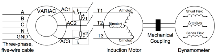
Figure 1: Electrical setup for no-load test. Please click here to view a larger version of this figure.
3. Locked-Rotor Test
Test the induction machine with a locked rotor in a manner similar to the short-circuit test of a transformer. Use this test to find the per-phase series resistances and leakage inductances. For this test, make sure the load dynamometer has all its terminals disconnected.
- Make sure the three-phase source is off.
- Check that the VARIAC is at 0%.
- Lock the rotor on the dynamometer side using a mechanical clamp or a zero-torque setting, if the dynamometer is digitally controlled.
- Note that the setup is still similar to that of Fig. 1, except with a locked rotor.
- Double-check that the circuit connections are as shown in Fig. 2.
- Turn on the three-phase source and the induction machine switch.
- Slowly and carefully increase the VARIAC until rated current is reached on one or both of the digital power meters.
- Record the power, voltage, and current readings from both meters.
- Set the VARIAC back to 0% then turn off the three-phase source. Leave the rest of the circuit intact.

Figure 2: Setup for load test.
4. Load Test
Use this test to trace the linear torque-speed characteristic of the induction machine. For this test, use the dynamometer with a shunt-field as a generator (more on this operating condition is given later in the DC machines video, but the armature is the generator output port).
- Make sure the three-phase source and induction machine switch are off.
- Check that the VARIAC is at 0%.
- Remove the locking clamp from the rotor shaft.
- Connect the circuit (Fig. 2). Use RL=300Ω but keep SD off.
- Do not use the series field.
- Check the circuit, then turn on the three-phase source and the induction machine switch.
- Quickly increase the VARIAC output until each of the digital power meters reads around 208 V.
- Record the power, voltage, and current readings from both meters.
- Measure the speed and label it as ω1. To measure the speed, adjust the "Coarse" frequency knob on the strobe light until the shaft looks almost stationary, and then fine-tune the frequency setting using the "Fine" knob.
- Record the torque reading and label it as T1.
- Note that this operating point (ω1, T1) is not the same as no load, because the field winding is also acting as a load in parallel with the armature. As SD is turned later and RL is decreased, the load is increased since the load current increases as RL decreases.
- Turn on SD. Measure the speed and label it as ω2.
- Record the torque reading and label it as T2.
- Turn off SD. Change RL to 200 Ω, then turn on SD.
- Measure the speed and label it as ω3.
- Record the torque reading and label it as T3.
- Turn on SD. Change RL to 100 Ω. Turn on SD.
- Measure the speed and label it as ω4.
- Record the torque reading and label it as T4.
- Set the VARIAC to 0%, turn off the three-phase source, and disassemble the circuit.
Sonuçlar
A common mistake in finding the equivalent circuit parameters of induction machines is to use the three-phase measured power in calculations of the per-phase equivalent circuit, while one third of the power should be used: three phases consume the measured power, and thus, one third of the power is in one phase.
Calculations of the equivalent circuit parameters are similar to those of the transformers, but it is common to split X1 and X2' per the NEMA frame of the machine. For example, if the motor is of NEMA frame A or D, then X1 and X2' are assumed to be equal, while if the motor is of NEMA frame B, then X1 and X2' are split as 40% and 60% of Xeq, respectively, and if the motor is of NEMA frame C, then X1 and X2' are split as 30% and 70% of Xeq, respectively. It is expected to find that X1 and X2' are 1-10% of Xm, R1 and R2' are on the order of mΩ to several Ω depending on the motor power rating, and RC would be on the order of tens to hundreds of Ω, as it is several orders of magnitude larger than R1 and R2'.
The linear region of the induction motor torque-speed curve is found using the load test and can be extrapolated from no-load to full- or rate-load conditions. A typical torque-speed curve is shown in Fig. 3 for several NEMA frames and the linear region is the right-most region close to the 90-100% speed.
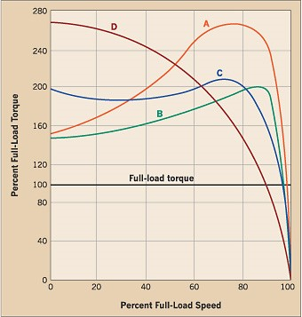
Figure 3: Typical torque-speed curves for various NEMA frames.
Başvuru ve Özet
Three-phase induction machines, especially induction motors, are the workhorses of modern industry. Appropriately characterizing an induction motor provides engineers and technicians with information on the motor's efficiency and torque-speed characteristics. These are essential in determining which motor size and frame best fits an application. Once a motor is characterized and the torque-speed curve is known from equivalent circuit parameters using the tests described, different NEMA frames have different curve shapes. For example, an elevator application requires high-starting torque; therefore, frames, such as NEMA frame D, are more suitable than A or B. When dealing with the induction motor's integral parts of larger systems that consume considerable amounts of energy (e.g., chillers), knowing the equivalent circuit parameters of a motor can provide good estimates of the motor's efficiency and its contribution to energy consumption in that larger system.
Etiketler
Atla...
Bu koleksiyondaki videolar:

Now Playing
AC Induction Motor Characterization
Electrical Engineering
11.6K Görüntüleme Sayısı

Electrical Safety Precautions and Basic Equipment
Electrical Engineering
144.6K Görüntüleme Sayısı

Characterization of Magnetic Components
Electrical Engineering
15.0K Görüntüleme Sayısı

Introduction to the Power Pole Board
Electrical Engineering
12.4K Görüntüleme Sayısı

DC/DC Boost Converter
Electrical Engineering
56.8K Görüntüleme Sayısı

DC/DC Buck Converter
Electrical Engineering
21.1K Görüntüleme Sayısı

Flyback Converter
Electrical Engineering
13.2K Görüntüleme Sayısı

Single Phase Transformers
Electrical Engineering
20.1K Görüntüleme Sayısı

Single Phase Rectifiers
Electrical Engineering
23.4K Görüntüleme Sayısı

Thyristor Rectifier
Electrical Engineering
17.5K Görüntüleme Sayısı

Single Phase Inverter
Electrical Engineering
17.9K Görüntüleme Sayısı

DC Motors
Electrical Engineering
23.4K Görüntüleme Sayısı

VFD-fed AC Induction Machine
Electrical Engineering
6.9K Görüntüleme Sayısı

AC Synchronous Machine Synchronization
Electrical Engineering
21.6K Görüntüleme Sayısı

AC Synchronous Machine Characterization
Electrical Engineering
14.2K Görüntüleme Sayısı
JoVE Hakkında
Telif Hakkı © 2020 MyJove Corporation. Tüm hakları saklıdır