Directional Solidification and Phase Stabilization
Обзор
Source: Sina Shahbazmohamadi and Peiman Shahbeigi-Roodposhti-Roodposhti, School of Engineering, University of Connecticut, Storrs, CT
Directional solidification zone melting is a metallurgical process in which a narrow region of a crystal (usually in the form of bar) is melted. The furnace moves along the rod shape sample, meaning that the molten zone is moved along the crystal and the molten zone is moved from one end of the bar to the other. This mechanism is widely used in alloys, however solute atoms tend to segregate to the melt. In this type of alloy, the impurities also concentrate in the melt, and move to one end of the sample along with the moving molten zone. Therefore, zone melting is used most extensively for commercial material refining. Fig. 1. shows how the high-impurity molten-zone moves from one side of the bar to the other. The vertical axis is the impurity concentration and the horizontal axis is the sample length. Due to the tendency for impurities to segregate to the molten region, its concentration in the melt is higher than in the solid. Therefore, as the molten materials travel to the end of bar, the impurity will be transported to the end of bar and leave the high purity solid material behind it.

Figure 1: Schematic of the composition change during zone melting directional solidification.
In this study, a zone melting directional solidification apparatus will be employed to synthesize stable structures of Pb-Cd alloys.
Принципы
In addition to material refining, zone melting directional solidification is capable of developing stable microstructures. However, having a diffusion process in the liquid (close to the solid liquid interface) may cause mixing and a convection current in the melt, leading to unstable microstructure formation. Stable phase development is particularly important in peritectic reactions.
Fig. 2 shows a schematic of a peritectic reaction in a phase diagram. As it has been demonstrated in Fig. 2, a peritectic reaction is a solidification reaction in which a solid phase (e.g. α) and liquid phase (L) will together form a second solid phase (β) as it is cooled (L +α β).The arrow in the figure shows the cooling process and how phases form.
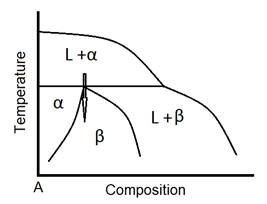
Figure 2: Schematic of peritectic reaction in a phase diagram.
Banding (Fig. 3), is a common structure in directionally solidified peritectic alloys at relatively lower growth rates resulting from oscillatory modes of convection in the liquid. The liquid, close to the growing interface, is undercooled with respect to the other phase. Therefore, the primary phase cannot reach steady state, while the second phase nucleates and grows ahead of the primary phase. In a similar way, the primary phase prevents the second phase from reaching steady state by nucleating during the transient growth regime of the second phase leads toalternate bands of α and β phases, formed nearly parallel to the planner interface in the peritectic system. Banding structures have been observed in many peritectic systems including Fe-Ni, Sn-Cd, Zn-Cu, Sb-Sn, and Pb-Bi. The width of individual layer, space between them and their stability are highly influenced by growth velocity and nucleation temperature. In addition, composition ranges and convection in the liquid can alter the layer structure.

Figure 3: Schematic of banded structure (white: α, black: ß, G.D.: Growth Direction).
In this study, we aim to employ the zone-melting directional solidification furnace with a mechanism to avoid the influence of convection. The furnace (Fig. 4.) has been designed and developed here at UConn. The process of solidification is in vertical direction. Therefore, if the solute has more density, it migrates bellow the melt. Then, a chill zone right after the furnace freezes the melted materials before they have enough time for convection/mixing. Therefore, this technique is limited to alloys with relatively heavy solute.
Alloys from Pb-Cd, Pb-Bi or Sn-Cd system should be directionally solidified at different thermal gradient and velocity in order to establish the growth conditions for mentioned systems in which diffusion in the solid phases is relatively slow. All samples should be made from pure metals (initial purity more than 99.99%).

Figure 4: Zone melting-freezing directional solidification furnace, developed at UConn.
Процедура
- Insert a 100 µm chromel-alumel thermocouple (in a 0.1 cm double bore mullite protection tube) in an 8 mm outside diameter Pyrex tube. The tube length should be around 30 cm. The thermocouple tip should be coated with a boron nitride slurry.
- Form rods of the desired composition by first melting the alloy in a crucible, and drawing the molten alloy into the Pyrex tube by means of a partial vacuum. For this, use a bulb attached to the end of the Pyrex tube to suck the melt into the tube.
- Place the sample in the vertical resistance zone melting and freezing apparatus (Fig. 4). The distance between the heating element and the following chill is set at 0.5 cm.
- Run the furnace to move vertically from bottom to top. At least three directional zone melting freezing pass is suggested.
- Remove the sample from the Pyrex tube (break the tube) and polish it for microstructure characterizations. For polishing, use the three-step SiC papers (600, 800 and 1200) followed by three steps of Alumina/colloidal silica abrasive particles (3µm, 1µm and 0.05 µm).
- Analyze the microstructures using optical microscopy.
Результаты
Figs. 5 and 6 show the microstructures developed from directional zone melting solidification of Pb-55Cd alloy revealed by optical microscope, at two different G/V ratios (G: thermal gradient, V: velocity of the furnace movement along the Pyrex tube).
At low ratio (G/V=1.03×106 (oC.Sec/Cm2)) the microstructure consisted of branched dendrites of α phase in the matrix of ß phase. At moderate G/V ratio (G/V=1.55×106 (oC.Sec/Cm2) however, aligned stable microstructures (unbranched dendrites or cells) of α phase in matrix of ß phase are developed.

Figure 5: Longitudinal (left) and transverse (right) micrographs of Pb-55Cd alloy, taken at low ratio G/V=1.03×106 (oC.Sec/Cm2), showing how the stable microstructures develop during zone melting directional solidification.

Figure 6: Longitudinal micrograph of Pb-55Cd alloy, taken at moderate ratio G/V=1.55×106 (oC.Sec/Cm2), and showing how the aligned stable microstructures develop during zone melting directional solidification.
Заявка и Краткое содержание
This experiment demonstrates to employ a specific type of zone melting freezing directional solidification furnace to develop stable microstructures. Unlike the two phase unstable microstructure that is not in equilibrium at room temperature and the structure degrade over a period of months by diffusion at room temperature, the single phase structure obtained in sample grown does not undergo any change.
Sample with stable phases, developed by mentioned furnace may have wide applications in various industries including biosensors and semiconductors in which alloys with stable phases are necessary to avoid degradation during long time application. Moreover, the furnace may be employed at researches aimed to find the influence of convection on stable and metastable phase's formations.
Теги
Перейти к...
Видео из этой коллекции:

Now Playing
Directional Solidification and Phase Stabilization
Materials Engineering
6.5K Просмотры

Optical Materialography Part 1: Sample Preparation
Materials Engineering
15.3K Просмотры

Optical Materialography Part 2: Image Analysis
Materials Engineering
10.9K Просмотры

X-ray Photoelectron Spectroscopy
Materials Engineering
21.5K Просмотры

X-ray Diffraction
Materials Engineering
88.3K Просмотры

Focused Ion Beams
Materials Engineering
8.8K Просмотры

Differential Scanning Calorimetry
Materials Engineering
37.1K Просмотры

Thermal Diffusivity and the Laser Flash Method
Materials Engineering
13.2K Просмотры

Electroplating of Thin Films
Materials Engineering
19.7K Просмотры

Analysis of Thermal Expansion via Dilatometry
Materials Engineering
15.6K Просмотры

Electrochemical Impedance Spectroscopy
Materials Engineering
23.1K Просмотры

Ceramic-matrix Composite Materials and Their Bending Properties
Materials Engineering
8.1K Просмотры

Nanocrystalline Alloys and Nano-grain Size Stability
Materials Engineering
5.1K Просмотры

Hydrogel Synthesis
Materials Engineering
23.5K Просмотры
Авторские права © 2025 MyJoVE Corporation. Все права защищены