Pressure Transducer: Calibration Using a Pitot-static Tube
Обзор
Source: Shreyas Narsipur, Mechanical and Aerospace Engineering, North Carolina State University, Raleigh, NC
Fluid pressure is an important flow characteristic that is required to determine the aerodynamics of a system. One of the oldest and still existing pressure measurement systems is the manometer due to its accuracy and simplicity of operation. The manometer is generally a U-shaped glass tube that is partially filled with liquid, as shown in Figure 1. The U-tube manometer requires no calibration because it does not have any moving parts, and its measurements are functions of gravity and the liquid's density. Therefore, the manometer is a simple and accurate measurement system.

Figure 1. Schematic of a U-tube manometer.
Real-time pressure measurements are obtained in aircraft by connecting the stagnation and static pressure ports of a pitot-static probe, a device that is commonly used to measure fluid flow pressure, to the ports of a pressure measurement device. This allows pilots to obtain existing flight conditions and to warn them if any changes to the flight conditions occur. While manometers provide very accurate pressure readings, they are inherently bulky. A more realistic solution is needed to measure aircraft pressures, as one of the primary design objectives is to keep the overall aircraft weight as low as possible. Today, electromechanical pressure transducers, which convert the applied pressure to an electric signal, are widely used for pressure sensing applications on aircraft because they are small, lightweight, and can be placed almost anywhere in the airframe. The above characteristics not only help reduce weight but also reduce the amount of tubing required to connect the pitot-static probe to the transducer, thereby decreasing the data response time. Additionally, in experimental aircraft flight testing, miniature pressure transducers come in handy as they allow researchers to maximize pressure data collection without significantly adding to the weight of the aircraft. While different types of pressure transducers with varying measurement techniques exist, one of the more common types of transducer is the capacitive pressure transducer. As transducers are capable of only sending signals in terms of voltage and current, calibration of the transducer is required to relate the strength of a particular signal to the pressure that causes the transducer to generate the signal. The final curve fit that relates the transducer current or voltage to a physical measurement, in our case pressure, is commonly referred to as the transducer calibration curve.
In this experiment, a pitot-static probe is placed in a subsonic wind tunnel with the stagnation and static pressure ports connected to the total and static ports of both the U-tube manometer and the pressure transducer. The wind tunnel is then run at different dynamic pressure settings, and the corresponding pressure reading from the U-tube manometer, and current readings produced by the transducer are recorded. This data is then used to generate calibration curves for the pressure transducer.
Принципы
In order to measure the dynamic pressure, each leg of the U-tube manometer is connected to unknown pressures from the static and total pressure ports of the pitot-static tube. The resulting difference is given by the following equation:
 (1)
(1)
which translates to a difference in column height on the U-tube manometer. This difference in pressures, or dynamic pressure, can be calculated using the expression:
 (2)
(2)
where ρwater is the density of water (the fluid in the U-tube manometer), g is the acceleration due to gravity, and hmanometer is the difference in column heights in the U-tube manometer. In some cases, the manometer can have an offset due to insufficient amount of fluid in the chamber and the offset in height, hoff, will have to be accounted for in the above equation as:
 (3)
(3)
The pressure transducer is based on the working principle of a capacitor, which consists of two conductive plates separated by an insulator (Figure 2).

Figure 2. Schematics of a capacitor (A) and a capacitance pressure transducer (B).
Capacitance is measured using the equation:
 (4)
(4)
where μ is the dielectric constant of the material, A is the area of the plates, and d is the spacing between the plates. In a capacitance pressure transducer, one of the conductive plates is replaced by a flexible conducting diaphragm, as shown in Figure 2. When pressure is applied, the diaphragm deflects, which causes a change in d, thereby leading to a change in capacitance. The electronics in the transducer are calibrated to generate specific voltage changes for corresponding changes in capacitance, which in turn can be used to measure the current for a given applied pressure.
Процедура
1. Pressure Transducer Calibration
In this demonstration, a subsonic wind tunnel with a 2.6 ft x 3.7 ft test section and maximum dynamic pressure setting of 25 psf was used. A pre-calibrated pressure transducer was used to set the dynamic pressure in the wind tunnel test section, and a differential U-tube manometer with colored water and scale was used to measure fluid height (Figure 3). A differential pressure transducer (Figure 4), standard voltage supply (to power the transducer), and multimeter (to read the output current from the transducer) were also used, shown in Figure 5.
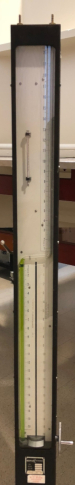
Figure 3. Differential pressure U-tube manometer.

Figure 4. Differential pressure transducer.
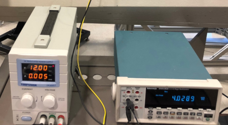
Figure 5. Power supply (left) and multimeter (right).
- Mount a standard pitot-static tube (Figure 6) from the top of the wind tunnel using a vertical sting mount. Ensure that the probe is at the center of the test section and is aligned in the direction of the flow with the primary port facing directly into the flow.

Figure 6. Pitot-static tube.
- Align the top of the manometer fluid to the double O-ring marker on the glass tube. If the reading on the main scale (in brown, Figure 3) does not correspond to zero, choose a different reference point, align the manometer fluid to the new reference, and record the offset in height (hoff).
- Connect the stagnation and static pressure outlets on the pitot-static tube to the corresponding ports on the U-tube manometer and the pressure transducer using flexible plastic tubing and T-channel connectors. Note that the pressure transducer can be mounted on any flat vertical surface as long as it is aligned in accordance with Figure 4.
- Secure the wind tunnel doors and switch-on all the systems.
- Take the reading for the no-air flow condition (zero reading).
- Start the wind tunnel and set the dynamic pressure in the test section to 1psf.
- Record the data corresponding to Table 1.
- Increase the dynamic pressure setting in the wind-tunnel in steps of 1psf up to a maximum setting of 20psf and repeat step 1.7 at each dynamic pressure setting.
- To check for transducer hysteresis, decrease the dynamic pressure in steps of 1psf down to 0psf and repeat step 1.7 at each dynamic pressure setting.
- On completion of the test, shut down all systems.
Table 1. Data collected for the pressure calibration experiment
| Ptransducer (psf) |
hmanometer (in) |
Itransducer (mA) |
| WT transducer | manometer | multimeter |
Результаты
The following constants were used in the analysis: water density, ρwater: 61.04 lb/ft3; acceleration due to gravity, g: 32.15 ft/s2; and manometer off-set, hoff = 0.8 in. The variation in manometer data for increasing and decreasing dynamic pressures (with and without correcting for the instrument off-set) is shown in Figure 7. Figure 8 shows a plot of the transducer current readings against the manometer pressure, which was calculated using Equation 3.
In order to obtain the calibration curve for the pressure transducer, two linear curves are fitted through the increasing and decreasing data points, respectively. The corresponding linear fit equations are:
 (5)
(5)
 (6)
(6)
The equations for the increasing and decreasing curves are almost similar, and the two curves align with each other, as observed in Figure 8. Therefore, it can be deduced that the pressure transducer does not have any hysteresis. A single calibration equation relating the current to the pressure (Equations 5 or 6) can be used for the transducer, thereby removing the necessity of using the bulky U-tube manometer system for all future pressure measurements.
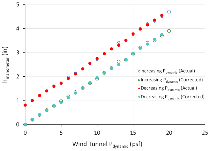
Figure 7. Variation of manometer fluid height with wind tunnel dynamic pressure. Please click here to view a larger version of this figure.
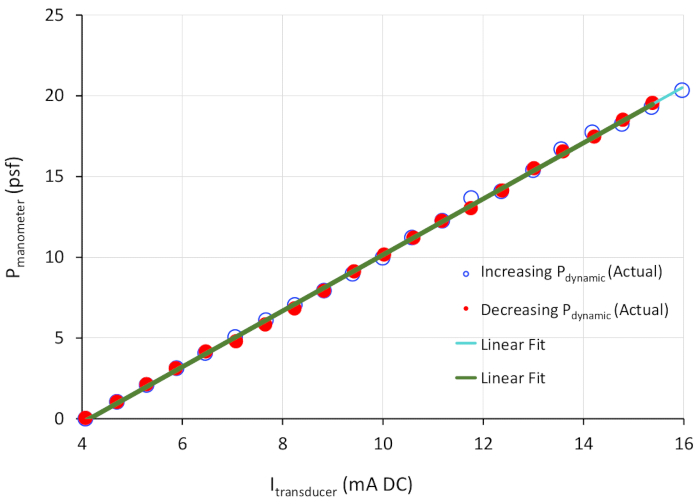
Figure 8. Calibration curves for the pressure transducer. Please click here to view a larger version of this figure.
Заявка и Краткое содержание
Electromechanical transducers are popular replacements for some of the bulkier measurement systems. However, transducers need to be calibrated regularly using standardized measuring devices in order to be effective experimental tools. In this experiment, an off-the-shelf capacitive type electromechanical pressure transducer was calibrated by comparing the current signals generated by the transducer for a range of dynamic pressure conditions in a subsonic wind tunnel to the pressure measurements from a U-tube manometer. Results showed that a linear relationship exists between the transducer's current signal and pressure with negligible sensor hysteresis. A single calibration equation relating the transducer current output to pressure was obtained.
Modern electromechanical measurement systems provide a path to automating experimental data acquisition and can be used in real-time static and dynamic systems for data monitoring and analysis. However, proper calibration practices, like the one demonstrated in this experiment, are necessary to help users obtain accurate and repeatable data using said sensors.
Теги
Перейти к...
Видео из этой коллекции:

Now Playing
Pressure Transducer: Calibration Using a Pitot-static Tube
Aeronautical Engineering
8.5K Просмотры

Aerodynamic Performance of a Model Aircraft: The DC-6B
Aeronautical Engineering
8.3K Просмотры

Propeller Characterization: Variations in Pitch, Diameter, and Blade Number on Performance
Aeronautical Engineering
26.2K Просмотры

Airfoil Behavior: Pressure Distribution over a Clark Y-14 Wing
Aeronautical Engineering
21.0K Просмотры

Clark Y-14 Wing Performance: Deployment of High-lift Devices (Flaps and Slats)
Aeronautical Engineering
13.3K Просмотры

Turbulence Sphere Method: Evaluating Wind Tunnel Flow Quality
Aeronautical Engineering
8.7K Просмотры

Cross Cylindrical Flow: Measuring Pressure Distribution and Estimating Drag Coefficients
Aeronautical Engineering
16.1K Просмотры

Nozzle Analysis: Variations in Mach Number and Pressure Along a Converging and a Converging-diverging Nozzle
Aeronautical Engineering
37.9K Просмотры

Schlieren Imaging: A Technique to Visualize Supersonic Flow Features
Aeronautical Engineering
11.4K Просмотры

Flow Visualization in a Water Tunnel: Observing the Leading-edge Vortex Over a Delta Wing
Aeronautical Engineering
8.0K Просмотры

Surface Dye Flow Visualization: A Qualitative Method to Observe Streakline Patterns in Supersonic Flow
Aeronautical Engineering
4.9K Просмотры

Pitot-static Tube: A Device to Measure Air Flow Speed
Aeronautical Engineering
48.7K Просмотры

Constant Temperature Anemometry: A Tool to Study Turbulent Boundary Layer Flow
Aeronautical Engineering
7.2K Просмотры

Real-time Flight Control: Embedded Sensor Calibration and Data Acquisition
Aeronautical Engineering
10.2K Просмотры

Multicopter Aerodynamics: Characterizing Thrust on a Hexacopter
Aeronautical Engineering
9.1K Просмотры
Авторские права © 2025 MyJoVE Corporation. Все права защищены