Propeller Characterization: Variations in Pitch, Diameter, and Blade Number on Performance
Przegląd
Source: Shreyas Narsipur, Mechanical and Aerospace Engineering, North Carolina State University, Raleigh, NC
A propeller is a twisted airfoil, where the angle of the chord changes with respect to the location, along the radial station, as shown in Figure 1. Propellers are widely used in aircraft and watercraft propulsion systems thereby necessitating detailed characterizations of propellers to design high performance vehicles.

Figure 1. Chord, thickness, and pitch at a radial station.
One of the defining characteristics of a propeller is the pitch/twist. The pitch of the propeller, generally given in units of length, is the theoretical distance the propeller will travel through the air in one single revolution. However, due to the drag force on the aircraft and the propeller, the propeller never travels its theoretical distance. The actual distance travelled is referred to as the effective pitch of the propeller, and the difference between the theoretical or geometric pitch and the effective pitch is referred to as propeller slip, as illustrated in Figure 2.

Figure 2. Representation of pitch and slip.
In this demonstration, seven propellers are characterized using a propeller test rig in a subsonic wind tunnel. This is followed by a detailed parametric study to analyze the effects of variations in pitch, diameter, and number of blades on propeller performance.
Zasady
There are two main propeller types: fixed pitch and variable pitch. Fixed pitch propellers are designed for one optimum operating condition and are efficient; they have a high power output to power input ratio for a given airspeed and RPM, which in most cases is the aircraft cruise conditions. However, during take-off and landing, when the RPM and airspeeds are lower, the fixed pitch propeller is highly inefficient. Variable pitch propeller blades offer a solution to the fixed pitch problem by allowing the pilot to change the propeller pitch to maximize propeller efficiency for any operating condition. It is for this reason that in larger propeller aircrafts, where fuel efficiency is a dominant factor, variable pitch propellers are used to maximize efficiency.
Advanced ratio, coefficient of thrust, coefficient of torque, coefficient of power, and propeller efficiency are important non-dimensional parameters required to characterize a propeller. Based on these parameters, the propeller, air-brake, and windmill regimes, which are the different operating regimes of a propeller, can be identified. In the propeller regime, the propeller is producing positive thrust and torque. The air-brake regime starts when thrust goes negative while torque remains positive. In this regime, the propeller slows the system down. Lastly, when both thrust and torque drop below zero, the propeller is in the windmill regime. Here, the airflow controls the propeller as it produces forces on the propeller of which the motor/engine driving the propeller cannot overcome. The propeller efficiency is meaningless beyond the propeller region.
It is always desirable to operate the propeller in the high-efficiency propeller regime for a given airspeed and RPM. As mentioned previously, fixed pitch propellers are generally designed to operate at their highest efficiencies during cruise flight, and while they can operate at lower velocities, such as during take-off and landing, the efficiency is very low. Variable pitch propellers can be adjusted to obtain the highest efficiencies possible in the propeller regime depending on the flight regime (take-off, cruise, or landing), thereby maximizing the aircraft's fuel efficiency.
In addition to propeller pitch, the number of propeller blades plays an important role in setting the thrust available from the propeller. Generally, if there are design constraints on the diameter or pitch of the propeller, increasing the number of blades can increase the amount of thrust produced. However, the extra thrust can come at the cost of propeller efficiency, necessitating the need for a detailed analysis.
The advanced ratio, J, which is a parameter to normalize freestream velocity (V∞) on the propeller rate of rotation (n) and diameter (D), is given by the following equation:

Freestream flow velocity can be measured using the equation:

where ρ is the freestream density.
The thrust coefficient, CT, is a non-dimensional measure of propeller thrust, T, and is given by the equation:

Similarly, the torque, CQ, and power, CP, coefficients, the non-dimensional measures of propeller torque and the output power, respectively, are given by the equations:
where τ is the torque and P is the power supplied to the brushless DC motor to run the propeller. The power, P, can be calculated as the product of voltage, V, and current, I:

Finally, propeller efficiency can be expressed as:

Procedura
1. Measuring propeller characteristics in a subsonic wind tunnel
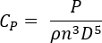
- Set up the propeller test rig in the subsonic wind tunnel using a 4-axis sting mount, as shown in Figure 3. A wind tunnel with a 2.6 ft x 3.7 ft test section and maximum dynamic pressure setting of 25 psf was used in this demonstration.
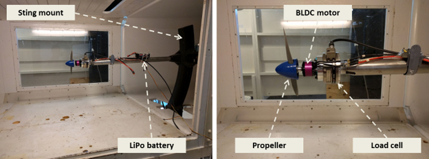
Figure 3. Propeller rig. Please click here to view a larger version of this figure.
- Attach a 6-axis load cell to the rig. This will be used to measure thrust and torque.
- Secure a brushless DC motor to the rig, then attach the first propeller.
- Connect the DC motor to the electronic speed controller and the pulsed-width modulated signal generator, which controls the speed of the motor.
- Connect a power analyzer, which will measure the current and voltage supplied to the motor, and connect it to a lithium polymer battery.
- Use a spirit level to ensure that the sting-propeller setup is aligned in the direction of flow with zero pitch and zero yaw.
- Secure the wind-tunnel doors and switch on the main power.
- Turn on the wind tunnel, then switch on the signal generator and the load cell data acquisition system.
- Zero the forces on the load cell using virtual instrument software.
- Set the signal generator to run the motor at 10% throttle.
- Start recording a zero-reading with the wind tunnel off. Record the speed following data:
a. Propeller characteristics - number of blades, propeller diameter (in), and propeller pitch (in).
b. Speed (in terms of percent throttle) based on the signal generator configuration.
c. Dynamic pressure (psf) from the wind tunnel transducer.
d. Voltage (V) and current (A) supplied to the BLDC motor from the power analyzer.
e. Thrust (lb) and torque (in-lb) from the load cell.
f. Propeller RPM (rotations per minute). Note that the RPM reading can only be extracted at the end of the experiment. - Turn on the wind tunnel and vary the dynamic pressure from 0 psf to 10 psf in steps of 0.5 psf.
- At each setting, allow the wind tunnel to stabilize, then record the same data as listed above.
- Continue to increase the dynamic pressure setting in increments of 0.5 psf up to a dynamic pressure setting at which the thrust and torque become negative. Record all data at each increment.
- Reset the tunnel dynamic pressure back to zero, and turn off the wind tunnel
- Set the motor speed to 50% throttle and repeat steps 1.11 - 1.15.
- Set the motor speed to 100% throttle and repeat steps 1.11 - 1.15.
- Repeat the above procedure for all propellers, making sure to test speeds of 10%, 50% and 100% throttle up to a dynamic pressure where thrust and torque become negative.
- When all tests have been completed, plug-in the electronic speed controller to the programming kit, record all of the propeller RPM data.
- Shut down all of the systems.
Table 1. Propellers tested.
| Propeller Diameter x Pitch (in) | # of Blades | Material |
| 18 x 8 | 2 | APC |
| 16 x 8 | 2 | APC |
| 15 x 8 | 2 | APC |
| 15 x 10 | 2 | APC |
| 15 x 12 | 2 | APC |
| 18 x 8 | 2 | Wood |
| 18 x 8 | 4 | Wood |
Note that the fixed pitch propellers used in this study are defined by their diameter and pitch in inches. For example, an 18 x 8 propeller is an 18 in diameter propeller with a geometric pitch of 8 in.
Wyniki
A freestream density, ρ: 0.074 lb/ft3, was used to determine the results. The variation in coefficients of thrust, torque, power, and propeller efficiency for the two-blade, 18 x 8 in propeller is shown in Figure 4. The propeller, air-brake, and windmill regions are demarcated. The two-blade, 18 x 8 in propeller produces positive thrust up to an advanced ratio of 0.6 after which it transitions to the air-brake region until J  0.85. At and after this point, the propeller starts producing negative torque and behaves like a windmill. The propeller achieves its highest efficiency at J = 0.4.
Figure 4. Characteristics of a two-blade, 18 x 8 in propeller.
Figures 5-7 compare the CT, CQ, CP, and η behaviors for propellers with variations in diameter, pitch, and number of blades, respectively. As shown in Figure 5, varying propeller diameter while keeping the number of blades and propeller pitch a constant had a negligible effect on propeller efficiency, η. However, the CT, CQ, and CP for a given advanced ratio, J, increased slightly with decreasing propeller diameter.
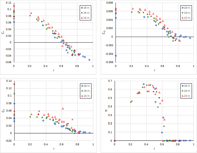
Figure 5. Comparison of characteristics for propellers of varying diameter. Please click here to view a larger version of this figure.
Varying propeller pitch significantly affected all parameters, as shown in Figure 6. In general, a high-pitch propeller produces more thrust, torque, and power for a given advanced ratio compared to a low-pitch propeller. Increasing propeller pitch also increased the range of the propeller region, i.e., the large region of positive thrust and torque. Lastly, the maximum operating efficiency occurred at a higher advanced ratio as propeller pitch increased.

Figure 6. Comparison of characteristics for propellers with varying pitch. Please click here to view a larger version of this figure.
Figure 7 shows that doubling the number of blades lead to a significantly higher amount of thrust and torque. While the propeller region is similar, the four-blade propeller starts behaving like a windmill at a higher advanced ratio compared to the two-blade propeller. Also, the two-blade propeller is slightly more efficient than its four-blade counterpart.
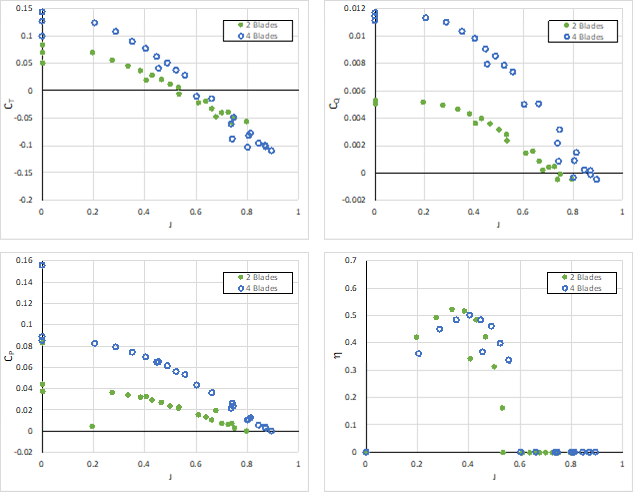
Figure 7. Comparison of characteristics for propellers varying in number of blades. Please click here to view a larger version of this figure.
Wniosek i Podsumowanie
Propellers are used to power small-scale aircraft and provide a simple method to provide thrust. They can be attached to an electric or reciprocating engine, where they convert rotational speed to thrust for propulsion. In this demonstration, seven propellers with varying pitch, diameter, and number of blades were characterized using a propeller test-rig mounted in a subsonic wind tunnel. For each propeller, the propeller, air-brake, and windmill regions of operation were identified. A parametric study conducted to study the effects of propeller diameter showed a slight decrease in thrust and torque with decreasing diameter. However, propeller pitch has a significant effect on the thrust and torque characteristics with high-pitch propellers having a clear advantage. Additionally, the extent of the propeller region deceases with decreasing pitch. Finally, increasing the number of blades increases the thrust, torque, and power with a slight decrease in propeller efficiency.
Selection of the appropriate propulsion system (engine/motor-propeller combination) for aircrafts or watercrafts is required to attain a high performance and efficient aerial or water vehicle. Detailed propeller characteristic data provide engineers an accurate way to assess flight performance parameters across all operating speeds of the aircraft/watercraft to correctly determine the optimum propulsion system.
Tagi
Przejdź do...
Filmy z tej kolekcji:

Now Playing
Propeller Characterization: Variations in Pitch, Diameter, and Blade Number on Performance
Aeronautical Engineering
26.2K Wyświetleń

Aerodynamic Performance of a Model Aircraft: The DC-6B
Aeronautical Engineering
8.3K Wyświetleń

Airfoil Behavior: Pressure Distribution over a Clark Y-14 Wing
Aeronautical Engineering
21.0K Wyświetleń

Clark Y-14 Wing Performance: Deployment of High-lift Devices (Flaps and Slats)
Aeronautical Engineering
13.3K Wyświetleń

Turbulence Sphere Method: Evaluating Wind Tunnel Flow Quality
Aeronautical Engineering
8.7K Wyświetleń

Cross Cylindrical Flow: Measuring Pressure Distribution and Estimating Drag Coefficients
Aeronautical Engineering
16.1K Wyświetleń

Nozzle Analysis: Variations in Mach Number and Pressure Along a Converging and a Converging-diverging Nozzle
Aeronautical Engineering
37.9K Wyświetleń

Schlieren Imaging: A Technique to Visualize Supersonic Flow Features
Aeronautical Engineering
11.4K Wyświetleń

Flow Visualization in a Water Tunnel: Observing the Leading-edge Vortex Over a Delta Wing
Aeronautical Engineering
8.0K Wyświetleń

Surface Dye Flow Visualization: A Qualitative Method to Observe Streakline Patterns in Supersonic Flow
Aeronautical Engineering
4.9K Wyświetleń

Pitot-static Tube: A Device to Measure Air Flow Speed
Aeronautical Engineering
48.7K Wyświetleń

Constant Temperature Anemometry: A Tool to Study Turbulent Boundary Layer Flow
Aeronautical Engineering
7.2K Wyświetleń

Pressure Transducer: Calibration Using a Pitot-static Tube
Aeronautical Engineering
8.5K Wyświetleń

Real-time Flight Control: Embedded Sensor Calibration and Data Acquisition
Aeronautical Engineering
10.2K Wyświetleń

Multicopter Aerodynamics: Characterizing Thrust on a Hexacopter
Aeronautical Engineering
9.1K Wyświetleń
Copyright © 2025 MyJoVE Corporation. Wszelkie prawa zastrzeżone