Single Phase Rectifiers
Przegląd
Source: Ali Bazzi, Department of Electrical Engineering, University of Connecticut, Storrs, CT.
A DC power supply is generally considered to be a device that supplies DC, or unidirectional, voltage and current. Batteries are one such power supply, however, they are limited in terms of lifetime and expense. An alternative method to providing unidirectional power is to transform AC line power to DC power using a rectifier.
A rectifier is a device that passes current in one direction, and blocks it in the other direction, enabling the transformation of AC to DC. Rectifiers are important in electronic circuits as they only allow current in a certain direction after a certain threshold forward voltage across them is overcome. A rectifier can be a diode, a silicon controller rectifier, or other types of silicon P-N junctions. Diodes have two terminals, the anode and the cathode, where current flows from anode to cathode. Rectifier circuits use one or more diodes that change AC voltages and currents, which are bipolar, to unipolar voltages and currents that can be easily filtered to achieve DC voltages and currents.
Zasady
Diode rectifiers are two-terminal semiconductor devices that pass current in one direction and block it in the other direction. Current passes from the anode to the cathode but not from the cathode to the anode. There is typically some leakage current in the blocking direction (cathode to anode), but it is very low. Diodes blocking current flow thus need to block a certain voltage level across from the cathode to the anode, so diodes are rated for their current carrying capability and their voltage blocking capability. When voltage across the diode terminals exceeds that voltage blocking rating, the diode operates in the breakdown region where it breaks and passes current both ways. The fact that diodes pass current in one direction leads to rectification capabilities where AC can be converted to DC.
Half-wave rectifiers (Fig.1 and Fig. 2) only pass half of the AC input voltage to the output while they block the negative half by providing a zero-output voltage. Full-wave rectifiers (Fig. 3 and Fig. 4) flip the polarity of the negative half to become positive in addition to passing the positive half. Though the outputs of these rectifiers are not smooth, they are by definition DC outputs, as the current flows in only one direction. However, these output waveforms are typically filtered in order to smooth the resulting output voltage.
The objective of this experiment is to study half-wave and full-wave single-phase rectifier operation for different load types. Rectification, along with the turn-off characteristics of diodes, are observed when the diode current reaches zero. Filtering the DC output voltage using an electrolytic capacitor is also studied.
Procedura
ATTENTION: During this experiment, do not touch any part of the circuit while energized. The AC source is only grounded as shown in Fig. 1 and 2 when the function generator is a source. Do NOT ground the VARIAC.
1. AC Source Setup
For this experiment, two AC sources are used; a variable transformer (VARIAC) at a low frequency of 60 Hz and a function generator with 10 V peak sinusoidal output and 1 kHz frequency.
- Before starting, connect the differential probe to one scope channel, and a regular probe to the other channel.
- Adjust the buttons on the probes as follows: differential probe at 20X (or 1/20) and the regular probe at 10X. Do not forget to turn ON the differential probe.
- On each channel's menu on the scope, set the probe to be at 10X. For the differential probe, manually multiply any measurements or results by two to reach the 20X desired.
- To set up the function generator, make sure the 50 Ω OUTPUT is connected to a BNC-to-alligator cable.
- Connect the alligator clips to a regular scope probe to observe the function generator output.
- Set the output to be a sinusoid at 10 V peak and 1 kHz frequency with zero DC offset.
- Observe the function generator output and adjust its settings to achieve the desired output waveform.
- Once your signal is set, disconnect the BNC connector but keep the function generator ON to maintain its settings. Disconnect the scope probe from the generator output.
- To setup the VARIAC, make sure the VARIAC output (looks like a regular receptacle) is not connected to any cable.
- Keep the VARIAC OFF and make sure its knob is set to zero.
- Slowly adjust the VARIAC knob to 5% output. This should yield around 10V peak voltage.
Half-Wave Rectifier
2. Resistive Load with High Frequency Input
- Use the function generator as the AC source but keep it disconnected from the circuit for now.
- On the proto board, build the circuit shown in Fig.1. The diode (D) is 2A01G-T rated for 50 V and 2 A while the load resistor (R) is 51 Ω.
- Make sure the diode polarity is correct. The dash on the diode is at the cathode.
- Before connecting the differential probe to the circuit, tie the probe's terminals together and adjust its measured waveform on the screen to show zero offset voltage.
- Connect the differential voltage probe across the load resistor to observe the output voltage Vout.
- Connect a regular probe across the AC side to observe the input voltage Vin.
- Connect the function generator to the circuit.
- Adjust the time base on the scope to show Vin and Vout for up to four fundamental cycles of Vin. Make a copy of the waveforms.
- Zoom in at the diode turn-off region and make a copy of the waveforms.
- Disconnect the function generator and remove the differential probe for load modifications. Keep the rest of the circuit and connections as they are.
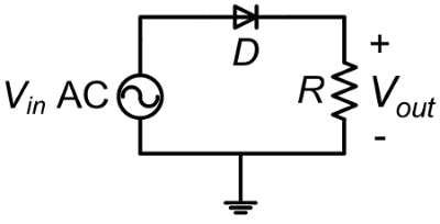
Figure 1: Half-wave rectifier with resistive load
3. Resistive-Inductive Load with High Frequency Input
- Using the same circuit in Fig. 1, connect a 4.7 mH inductor (L) in series with the resistive load as shown in Fig. 2.
- Connect the differential voltage probe across the load resistor to observe the resistor voltage Vout which has the same waveform shape as the R-L load current Iout.
- Turn the function generator output ON.
- Adjust the time base on the scope to show Vin and Vout for up to four fundamental cycles of Vin. Make a copy of the waveforms.
- Zoom in at the diode turn-off region and observe the delay in the turn-off time. Make a copy of the waveforms.
- Turn the function generator output OFF and disconnect it from the circuit.
- Remove the inductor L and keep the rest of the circuit as it is.

Figure 2: Half-wave rectifier with R-L load
4. Resistive Load with Low Frequency Input
- Make sure the VARIAC output is at 5% and disconnected from the circuit. Connect the differential probe across the VARIAC, turn the VARIAC ON and slightly adjust its output to achieve 10 V peak.
- Capture the waveform on the scope to use as your reference input voltage observation.
- Turn the VARIAC OFF but do not change its voltage setting.
- Using the same circuit from Fig. 1, i.e. with the inductor disconnected and the resistor being the only load, connect the VARIAC output using the plug-banana cable.
- Connect the differential voltage probe across the load resistor to observe the output voltage, Vout.
- Turn ON the VARIAC output. Stay away from the circuit and observe the waveforms on the scope. If you need to debug your circuit, power the VARIAC OFF first.
- Adjust the time base on the scope to show Vout for up to four fundamental cycles. Make a copy of the waveform.
- Zoom in at the diode turn-off region and make a copy of the waveforms.
- Turn OFF the VARIAC and disassemble your circuit. Do NOT change the VARIAC voltage setting.
Full-Wave Rectifier
5. Resistive Load
- On the proto board, build the circuit shown in Fig. 3.
- Make sure the diode polarity is correct. The dash on the diode is at the cathode.
- Once the circuit is ready, connect the VARIAC output as the AC source.
- Connect the differential voltage probe across the load resistor to observe the output voltage Vout.
- Turn ON the VARIAC output. Stay away from the circuit and observe the waveforms on the scope. If you need to debug your circuit, power the VARIAC OFF first.
- Adjust the time base on the scope to show Vout for up to four fundamental cycles of Vin. Make a copy of the waveforms.
- Measure the peak-to-peak value of Vout by using the cursors.
- Keep the probe connections as they are and Turn OFF the VARIAC and disassemble your circuit.
- Do NOT change the VARIAC voltage setting.
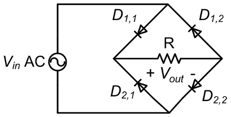
Figure 3. Full-wave rectifier with resistive load.
6. Resistive Load with Filtering Capacitor
- Using the same circuit in Fig. 3, connect an electrolytic capacitor (C) in parallel with the resistive load as shown in Fig. 4.
- Make sure the capacitor polarity is correct with the ( - ) terminal connected to negative side of the load.
- Turn ON the VARIAC output. Stay away from the circuit and observe the waveforms on the scope. Before debugging the circuit, power the VARIAC OFF.
- Adjust the time base on the scope to show Vout for up to four fundamental cycles of VIN. Make a copy of the waveforms.
- Measure the peak-to-peak value of Vout by using the cursors and the AC coupling option for that channel (AC coupling eliminates the DC offset of a signal).
- Return this to DC coupling once the measurement is made.
- Turn OFF the VARIAC.
- Disassemble the circuit and clean up the bench.

Figure 4. Full-wave rectifier with resistive load and capacitive filtering
Wyniki
It is expected that a resistive load coupled to a half-wave rectifier will only see the positive half-cycle of the input AC voltage since the diode rectifier can pass current in one direction. With a full-bridge rectifier, the input positive and negative half-cycles are rectified to be positive, but adding a capacitor will filter out most of the voltage ripple and provide the load with a clean DC voltage.
When an inductor is added in series with the load, it is expected that the diode turn off will be delayed. This can be explained as follows: Diodes turn off under two conditions (that are required to coexist) 1) the current in the diode has to go to zero, and 2) the voltage across the diode (Anode-to-cathode voltage) is below the turn-on threshold. When an inductor is in series with the load, it stores energy and will act as a current source when the source is not available or is going negative at the diode's anode side. Therefore, inductor current will maintain the diode as forward biased until the inductor energy is dissipated. Essential equations that govern basic rectifier circuits with input Vin=V0cos(ωt):
Single diode and resistive load: <Vout>=V0/π (1)
Diode bridge and resistive load: <Vout>=2V0/π (2)
Diode bridge, current source load: <Vout>=2V0/π (3)
Wniosek i Podsumowanie
Diode rectifiers are almost in every power supply, charger, variable frequency drive, and in many protection circuits. Most DC power supplies or adjustable AC power supplies use diode rectifiers to convert AC to DC, and then to adjustable AC if needed as in AC power supplies and variable frequency drives. Applications in power electronic converters are common for voltage blocking, and for freewheeling energy in inductors, electro-mechanical relays, and motor windings. Diode applications extend beyond power electronics applications to low power electronics, communication systems, and lighting applications.
Tagi
Przejdź do...
Filmy z tej kolekcji:

Now Playing
Single Phase Rectifiers
Electrical Engineering
23.4K Wyświetleń

Electrical Safety Precautions and Basic Equipment
Electrical Engineering
144.6K Wyświetleń

Characterization of Magnetic Components
Electrical Engineering
15.0K Wyświetleń

Introduction to the Power Pole Board
Electrical Engineering
12.4K Wyświetleń

DC/DC Boost Converter
Electrical Engineering
56.8K Wyświetleń

DC/DC Buck Converter
Electrical Engineering
21.1K Wyświetleń

Flyback Converter
Electrical Engineering
13.2K Wyświetleń

Single Phase Transformers
Electrical Engineering
20.1K Wyświetleń

Thyristor Rectifier
Electrical Engineering
17.5K Wyświetleń

Single Phase Inverter
Electrical Engineering
17.9K Wyświetleń

DC Motors
Electrical Engineering
23.3K Wyświetleń

AC Induction Motor Characterization
Electrical Engineering
11.6K Wyświetleń

VFD-fed AC Induction Machine
Electrical Engineering
6.9K Wyświetleń

AC Synchronous Machine Synchronization
Electrical Engineering
21.6K Wyświetleń

AC Synchronous Machine Characterization
Electrical Engineering
14.2K Wyświetleń
Copyright © 2025 MyJoVE Corporation. Wszelkie prawa zastrzeżone