AC Synchronous Machine Characterization
Przegląd
Source: Ali Bazzi, Department of Electrical Engineering, University of Connecticut, Storrs, CT.
Three-phase wound-rotor synchronous motors are less popular than permanent magnet rotor synchronous motors due to the brushes required for the rotor field. Synchronous generators are much more common and available in most existing power plants, as they have excellent frequency and voltage regulation. Synchronous motors have the advantage of almost 0% speed regulation due to the fact that the rotor speed is exactly the same as the stator's magnetic field speed, causing the rotor speed to be constant, irrespective of how much the motor's shaft is loaded. Thus, they are very suitable for fixed speed applications.
The objectives of this experiment are to understand the concepts of starting a three-phase synchronous motor, V-curves for various loads where the load affects the motor power factor, and the effect of loads on the angle between the terminal voltage and back e.m.f.
Zasady
Synchronous machines rely on the rotating magnetic field concept introduced for induction machines. Three-phase currents, flowing in the machine's stator, produce a rotating magnetic field of constant magnitude at a desired frequency. The difference between the synchronous and asynchronous machines is that the latter has shorted windings or a "squirrel cage" on the rotor side, while synchronous machines have a fixed magnetic field on the rotor side. This magnetic field is either provided by an exciter or by permanent magnets. Permanent magnet synchronous machines are becoming more common due to their high efficiency and compact size, but they typically utilize rare earth materials. The term synchronous is used because the rotor magnetic field, which is independent from the stator, locks to the rotating magnetic field and causes the rotor to spin at the same speed (or synchronous speed) as the stator's rotating magnetic field.
To start a three-phase wound-rotor synchronous motor, the field winding is shorted where the machine acts as an induction motor. Once the machine speed is close to synchronous speed, the short circuit is removed and a DC voltage is applied across the field winding. This locks the rotor and stator magnetic fields, and thus, rotor and stator synchronism is achieved. In this lab, the synchronous motor is started by having the top switch on its interface plate in the "Induction Start" position, and once the speed reaches steady state, the switch is flipped to the "Synchronous Run" position.
Procedura
1. DC Test
- Turn on the low-power DC power supply with a short circuit across its terminals.
- Limit the current on the low-power DC power supply to 1.8 A.
- Turn off the supply and disconnect the short circuit.
- Connect the supply terminals across ports 1 and 4 of the synchronous motor.
- Turn on the supply and measure the DC voltage and current. Vary the voltage as needed to reach a current of 1.8 A.
- Turn off the supply, then repeat the previous two steps for ports 2 and 5 and ports 3 and 6.
- Disconnect the low-power DC power supply.
2. Synchronous Machine Start-up
- Make sure the three-phase disconnect switch, synchronous motor switch, and DC motor switch are all off.
- Check that the VARIAC is at 0%.
- Wire the VARIAC to the three-phase outlet, and connect the setup shown in Fig. 1.
- Remember to set the 1 to 1000 scaling of the digital power meter current probe.
- Check that the "Start/Run" switch is in the "Start" position.
- Turn on the three-phase disconnect switch.
- Quickly increase the VARIAC output until the digital power meter reads around 115 V.
- Measure the armature current IAC1, armature voltage VAC1, real power, and power factor.
- Remember that the phase (line-to-neutral) voltage and phase current on phase "a" are being measured, so the power factor measurement on the power meter is correctly reflecting the per-phase power factor.
- Measure the torque and speed of the machine.
- Turn on the 125 V DC power supply. Make sure all connections are clear from the supply terminals.
- Press the supply "Start" button and set the supply output to 125 V.
- Flip the "Start/Run" switch to the "Run" position. Pay attention to how the machine sound changes. The machine sound becomes smoother as the rotor magnetic field locks to the stator rotating magnetic field.
- Record the armature current IAC1, armature voltage VAC1, real power, power factor, and the field voltage and current from the DC power supply display.
- Measure and record the torque and speed of the machine.
- Turn off the DC power supply, flip the "Start/Run" switch to the "Start" position, and set the VARIAC back to 0%.
- Turn off the three-phase disconnect switch. Leave the rest of the circuit intact.

Figure 1: A schematic of the setup to start the synchronous motor. Please click here to view a larger version of this figure.
3. Effect of Load on Torque Angle
- Make sure the three-phase disconnect switch, synchronous motor switch "S1," and DC motor switch "S2" are all off.
- Note that while "S1"is on the synchronous motor side, it is used to connect/disconnect the "RL" load across the DC machine terminals.
- Check that the VARIAC is at 0%.
- Connect the setup shown in Fig. 2 and set "RL" to 200 Ω.
- Check that the "Start/Run" switch is in the "Start" position.
- Turn on the three-phase disconnect switch.
- Quickly increase the VARIAC output until the digital power meter reads around 115 V.
- Turn on the 125 V DC power supply. Make sure all connections are clear from the supply terminals.
- Press the supply start button and set the supply output to 125 V.
- Flip the "Start/Run" switch to the "Run" position.
- Record the armature current IAC1, armature voltage VAC1, real power, power factor, and field voltage and current from the DC power supply display.
- Measure and record the torque and speed of the machine.
- Keep the strobe light on near the shaft and measure the initial angle δo.
- To set up the strobe light, plug it into a regular power outlet and turn it on.
- With the Coarse knob, adjust the speed reading on the strobe light to be close enough to 1,800 RPM, which is the synchronous speed of 1 four-pole 60 Hz machine. Synchronous speed is calculated in rounds per minute (RPM) as n=120xf/P where f is the frequency and P is the number of poles.
- Place the strobe light to face the motor shaft's edge, and adjust the Fine knob until the shaft appears stationary. The human eye is tricked to see the shaft as stationary by having the strobe light frequency (or speed reading) match the shaft speed.
- Turn on "S1" and repeat steps 3.9 to 3.11, but measure the new angle as δ1.
- Turn on "S2" and repeat steps 3.9 to 3.11, but measure the new angle as δ2.
- Turn off "S2" and change "RL" to 100 Ω.
- Turn on "S2" and repeat steps 3.9 to 3.11, but measure the new angle as δ3.
- Turn off the DC power supply, flip the "Start/Run" switch to the "Start" position, turn off "S1"and "S2," and set the VARIAC back to 0%.
- Turn off the three-phase disconnect switch. Leave the rest of the circuit intact.

Figure 2: A schematic of the setup to study the effect of load on torque angle. Please click here to view a larger version of this figure.
4. Effect of Field Current on Power Factor
This section investigates one side of the V-Curve.
- Make sure the three-phase disconnect switch, synchronous motor switch S1, and DC motor switch S2 are all off.
- Check that the VARIAC is at 0%.
- Connect the setup shown in Fig. 3, which is only different from Fig. 2 by adding the series field resistor "RF," and set "RL" to 200 Ω.
- Set "RF" to the 10 Ω position. "RF" does not require measurement for this experiment, since the goal is to vary field current only.
- Check that the "Start/Run" switch is in the "Start" position.
- Turn on the three-phase disconnect switch.
- Quickly increase the VARIAC output until the digital power meter reads 115 V.
- Turn on the 125 V DC power supply. Make sure all connections are clear from the supply terminals.
- Press the supply start button and set the supply output to 125 V.
- Flip the "Start/Run" switch to the "Run" position.
- For "RF" = 10, 6, 3, and 1, record the armature current IAC1, armature voltage VAC1, real power, power factor, field voltage and current from the DC power supply display.
- Measure and record the torque and speed of the machine.
- Reset "RF" to 10 Ω.
- Turn on "S1," and repeat steps 4.11 to 4.13.
- Turn on "S2," and repeat steps 4.11 to 4.13.
- Turn off "S2" and change "RL" to 100 Ω.
- Turn on "S2," and repeat steps 4.11 to 4.13.
- Turn off the DC power supply, flip the "Start/Run" switch to the "Start" position, and set the VARIAC back to 0%.
- Turn off the three-phase disconnect switch and disconnect the setup.
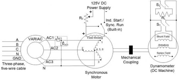
Figure 3: A schematic of the setup to study the effect of changing the field current. Please click here to view a larger version of this figure.
Wyniki
The DC phase resistance can be estimated from the DC test as the ratio of DC voltage to DC current when applied between a phase terminal and the neutral. The field resistance can be measured in a similar manner by applying DC voltage to the field winding and measuring the field current. The synchronous reactance (Xs), back e.m.f. of the machine (EA), and its related constant kφ can be found from the real power (P3φ) measurement into the machine: P3φ=3VφEAcos(δ)/Xs (ignoring the stator resistance Rs) and basic power flow equations for the per-phase equivalent circuit (Fig. 4).
V-curves determine the power factor of the machine as seen by the source (grid). The V-curves demonstrate that the machine can provide reactive power (leading power factor) under certain conditions, and therefore, acts like a capacitor that can enhance voltage stability on the grid. When operating under such a condition, the machine is termed "synchronous condenser."

Figure 4: A schematic of the per-phase equivalent circuit used for the representative results.
Wniosek i Podsumowanie
Synchronous machines are common in applications requiring constant speed on the motor's shaft with very tight speed regulations. Such applications include electrical clocks and hard disk drives, but extend to synchronous condensers, which are synchronous motors operating in the leading power factor region to provide reactive power to a load. Power factor correction is another term used with synchronous condenser applications. Note that the most common synchronous motors are permanent magnet motors, while the most common synchronous generators are wound-rotor synchronous generators.
Tagi
Przejdź do...
Filmy z tej kolekcji:

Now Playing
AC Synchronous Machine Characterization
Electrical Engineering
14.2K Wyświetleń

Electrical Safety Precautions and Basic Equipment
Electrical Engineering
144.6K Wyświetleń

Characterization of Magnetic Components
Electrical Engineering
15.0K Wyświetleń

Introduction to the Power Pole Board
Electrical Engineering
12.4K Wyświetleń

DC/DC Boost Converter
Electrical Engineering
56.8K Wyświetleń

DC/DC Buck Converter
Electrical Engineering
21.1K Wyświetleń

Flyback Converter
Electrical Engineering
13.2K Wyświetleń

Single Phase Transformers
Electrical Engineering
20.1K Wyświetleń

Single Phase Rectifiers
Electrical Engineering
23.4K Wyświetleń

Thyristor Rectifier
Electrical Engineering
17.5K Wyświetleń

Single Phase Inverter
Electrical Engineering
17.9K Wyświetleń

DC Motors
Electrical Engineering
23.4K Wyświetleń

AC Induction Motor Characterization
Electrical Engineering
11.6K Wyświetleń

VFD-fed AC Induction Machine
Electrical Engineering
6.9K Wyświetleń

AC Synchronous Machine Synchronization
Electrical Engineering
21.6K Wyświetleń
Copyright © 2025 MyJoVE Corporation. Wszelkie prawa zastrzeżone