Single Phase Transformers
Przegląd
Source: Ali Bazzi, Department of Electrical Engineering, University of Connecticut, Storrs, CT.
Transformers are stationary electric machines that step up or down AC voltage. They are typically formed of primary and secondary coils or windings, where the voltage on the primary is stepped up or down at the secondary, or the other way around. When a voltage is applied to one of the windings and current flows in that winding, flux is induced in the magnetic core, coupling both windings. With an AC current, AC flux is induced, and its rate of change induces voltage on the secondary winding (Faraday's law). Flux linkage between both windings depends on the number of turns of each winding; therefore, if the primary windings have more turns than the secondary winding, voltage will be higher on the primary than on the secondary, and vice versa.
This experiment characterizes a single-phase transformer by finding its equivalent circuit parameters. Three tests are performed: open-circuit test, short-circuit test, and the DC test.
Zasady
The transformer used in this experiment is rated at 115 V/24 V, 100 VA. The voltage rating comes from the ability of the insulation of each winding to safely handle specific voltages, while the VA rating or power (Watt) rating come from current handling capability of these windings, specifically wire thickness. It is important not to mix primary and secondary with high- and low-voltage nomenclature. For this experiment, the primary side is assumed to have the 115 V rating, while the secondary side is rated at 24 V. The 115 V side has two terminals labeled IN1 and IN2, while the secondary side has two terminals labeled OUT1 and OUT2.
The high-voltage side is commonly used for short-circuit testing to achieve more voltage resolution. For example, if a transformer is rated for 1200 V/120 V, a short-circuit on the 120 V probably has rated current flowing with less than 10% of the 1200 V, which makes a 0-120 V variable auto-transformer (VARIAC) on the 1200 V suitable for this test. The low-voltage side is commonly used for open-circuit testing, since this voltage is more accessible in the lab. Thus, this approach is followed as standard practice in this experiment.
The open-circuit test helps estimate the mutual inductance between two windings, as well as core power losses caused by flux induced in the core. The short-circuit test helps identify the leakage inductance of both windings, since maximum current is drawn in the short circuit, and some flux leaks from the core around the windings. The DC test helps measure wire resistance of both windings.
Procedura
1. DC Test
- Turn on the low-voltage DC power supply available on the bench.
- Set its voltage output to 0 V, and set the current limit to 0.8 A.
- Double-check the circuit connections, then connect the power supply output across the primary side windings (IN1 and IN2). Leave the secondary side windings (OUT1 and OUT2) open.
- Turn on the supply and slightly increase the voltage until the current limit is reached. Note that the supply might already be current-limited when the supply is turned on. Do not increase the current limit.
- Record the voltage and current readings from the power supply display.
- Set the voltage back to 0 V and disconnect the supply.
- Adjust the current limit to 4 A, then connect the supply output across the secondary side windings (OUT1 and OUT2). Leave the primary side windings (IN1 and IN2) open.
- Turn on the supply and slightly increase the voltage until the current limit is reached. Note that the supply might already be current-limited when the supply is turned on. Do not increase the current limit.
- Record the voltage and current readings from the power supply display. For this transformer, the input voltage is 3.5 V and the current is 0.8 A.
- Set the voltage back to 0 V, turn the supply off, and disconnect it.
- Measure the resistance across the primary windings with a multi-meter.
- Measure the resistance across the secondary windings with a multi-meter.
- It is common to have the higher voltage side resistance to be higher than the lower voltage side resistance due to the fact that power on both sides is ideally equal, and higher voltage means lower current and thus lower resistance. The DC test and measured resistance on the multi-meter should match closely.
2. Open-circuit Test
- Make sure the three-phase source is off.
- Connect the circuit for the open-circuit test (Fig. 1). Use a digital power meter.
- Make sure the VARIAC is at 0%.
- Double-check that the circuit connections are as expected from Fig. 1, and then turn on the three-phase source.
- Slowly adjust the VARIAC knob until the voltage reading on the digital power meter reaches 24 V.
- Record the voltage, current, real power, and power factor of the power meter.
- Set the VARIAC back to 0%, turn off the three-phase source, and disconnect the VARIAC output.
- In the open-circuit or no-load test, the magnetizing reactance (Xm) and core loss resistance (RC) are found from the current (IOC), voltage (VOC), and power (POC) measurements as follows:
RC= VOC2/POC (1)
and Xm= VOC2/QOC (2)
where QOC2=(VOCIOC)2 - POC2 (3)
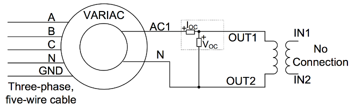
Figure 1: DC test schematic. Please click here to view a larger version of this figure.
3. Short-circuit Test
- Make sure the three-phase source is off.
- Connect the circuit for the short-circuit test (Fig. 2). Make sure IN1 and IN2 are connected to the VARIAC output.
- Make sure the VARIAC is at 0%.
- Calculate the rated input current of the transformer. This is found by dividing the VA rating by the voltage rating on the input side. For example, if the input is 115 V and the VA rating is 100 VA, the input current rating is 100/115= 0.87 A.
- Check the circuit, and then turn on the three-phase source.
- Slowly and carefully adjust the VARIAC knob until the current reading on the digital power meter reaches rated input current.
- Record the voltage, current, real power, and power factor on the power meter.
- Set the VARIAC back to 0%, turn off the disconnect switch, and disconnect the VARIAC output. Keep the VARIAC three-phase cable connected.
- Remove the short circuit placed across the transformer secondary.
- In the short-circuit test, the leakage reactance (X1+X2'=Xeq) and wire resistance (R1+R2'=Req) of both windings are found from the current (ISC), voltage (VSC), and power (PSC) measurements as follows:
Req=PSC/ISC2 (4)
and Xeq= QSC/ISC2 (5)
where QSC2=(VSC ISC)2 - PSC2 (6) - X1 is assumed to be equal to X2', while R1 and R2' can be used from the DC test (or at least one of them). If the DC test is not performed, it is common to assume that R1 and R2' are equal.
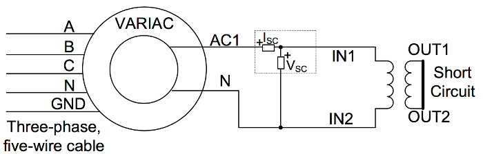
Figure 2: Short-circuit test schematic. Please click here to view a larger version of this figure.
4. Load Test
Load tests show how the current and voltage values correlate between the input and output sides of the transformer where ideally, V1/V2 = I2/I1 = N1/N2 = a where N is the number of turns, subscripts 1 and 2 are for the primary and secondary sides, respectively, and a is the turns ratio. The impedance on the secondary side reflected to the primary side is R'=a2R or X'=a2X.
- Make sure the three-phase source is off.
- Connect the circuit for the load test (Fig. 3). Make sure IN1 and IN2 are connected to the VARIAC output.
- Make sure the VARIAC is at 0%.
- Connect an oscilloscope differential voltage probe across the primary with a 1/200 setting. Adjust the probe measurement for 0 V offset with an appropriate scaling factor.
- Connect an oscilloscope current probe to measure the load current. Adjust the probe measurement for 0 mV offset with a 1X scaling factor for a 100 mV/A setting.
- Check the circuit, and then turn on the three-phase disconnect switch.
- Slowly adjust the VARIAC knob until VP reads 115 V.
- Record the voltage, current, real power, and power factor of both digital power meters.
- Capture the oscilloscope screen with at least three cycles shown.
- Turn off the three-phase source and set the VARIAC at 0%.
- Replace the 100 Ω resistor with three 100 Ω resistors in parallel.
- Turn on the three-phase source and slowly adjust the VARIAC knob until VPreads 115 V.
- Record the two digital power meter readings only (no oscilloscope screen capture).
- Set the VARIAC back to 0%, turn off the disconnect switch, and disconnect the setup.
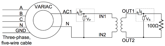
Figure 3: Load test schematic. Please click here to view a larger version of this figure.
Wyniki
By performing the DC, open-circuit, short-circuit, and load tests, the transformer's equivalent circuit parameters were identified; therefore, simulating, operating, and analyzing realistic transformer behavior become possible.
The short circuit test is usually performed by applying an increasing voltage on the high voltage side, since only small voltages on that side may cause rated current to flow on the shorted low voltage side. This is useful in operating the transformer at rated current and, therefore, testing for current carrying capability.
For this test, the short circuit voltage is 11.9 V, the short circuit current is 0.865 A, and the short circuit power is 7.11 W. The short circuit measurements are then used to calculate leakage reactance, which is 9.94Ω in this case. The resulting primary side and reflected side reactances are each 4.97Ω. The total wire resistance is calculated as 9.502Ω. Subtracting the resistance of the primary winding (4.375Ω) gives 5.127
As for the open-circuit test, it is useful in ensuring that transformer voltage insulation capabilities are met when running rated voltages. Other tests, such as high-pot insulation tests for insulation material breakdown, mechanical vibration tests, etc., are also performed but for more advanced applications.
For this transformer, the open circuit voltage is 23.8 V, the open circuit current is 335.5 mA and the open circuit power is 2.417 W. From these measurements, the core loss resistance, Rc, and mutual reactance, Xm, can be calculated as 234.35Ω and 74.67Ω respectively.
Wniosek i Podsumowanie
The described tests are critical in evaluating the impedance of a transformer and in determining its equivalent circuit parameters. Since transformer applications vary from simple chargers to high power AC transmission, appropriately characterizing different transformers for various applications is essential. Transformer impedance is used in power systems to determine possible fault impedances on either side of a transformer, approximate the efficiency of a transformer, calculate its line and load regulation, and simulate the transformer as part of larger electrical systems.
Tagi
Przejdź do...
Filmy z tej kolekcji:

Now Playing
Single Phase Transformers
Electrical Engineering
20.1K Wyświetleń

Electrical Safety Precautions and Basic Equipment
Electrical Engineering
144.6K Wyświetleń

Characterization of Magnetic Components
Electrical Engineering
15.0K Wyświetleń

Introduction to the Power Pole Board
Electrical Engineering
12.4K Wyświetleń

DC/DC Boost Converter
Electrical Engineering
56.9K Wyświetleń

DC/DC Buck Converter
Electrical Engineering
21.1K Wyświetleń

Flyback Converter
Electrical Engineering
13.2K Wyświetleń

Single Phase Rectifiers
Electrical Engineering
23.4K Wyświetleń

Thyristor Rectifier
Electrical Engineering
17.5K Wyświetleń

Single Phase Inverter
Electrical Engineering
17.9K Wyświetleń

DC Motors
Electrical Engineering
23.4K Wyświetleń

AC Induction Motor Characterization
Electrical Engineering
11.6K Wyświetleń

VFD-fed AC Induction Machine
Electrical Engineering
6.9K Wyświetleń

AC Synchronous Machine Synchronization
Electrical Engineering
21.6K Wyświetleń

AC Synchronous Machine Characterization
Electrical Engineering
14.2K Wyświetleń
Copyright © 2025 MyJoVE Corporation. Wszelkie prawa zastrzeżone