Tests of Hardened Concrete in Tension
Overview
Source: Roberto Leon, Department of Civil and Environmental Engineering, Virginia Tech, Blacksburg, VA
In a previous laboratory focused on concrete in compression, we observed that concrete can withstand very large stresses under uniaxial compressive forces. However, the failures observed were not compressive failures but failures along shear planes where maximum tensile forces occur. Thus, it is important to understand the behavior of concrete in tension and particularly its maximum strength as that will govern both its ultimate and service behavior. From the ultimate standpoint, combinations of tension and shear stresses will lead to cracking and immediate and catastrophic failure. For that reason, concrete is seldom if ever used in an unreinforced condition in structural applications; most concrete members will be reinforced with steel so that these cracks can be stopped and the crack widths limited. The latter is important from the serviceability standpoint because controlling crack widths and distribution is the key to durability, as this will impede deicing salts and similar chemicals from penetrating and corroding the reinforcing steel.
The objectives of this experiment are threefold: (1) to conduct tensile split cylinder tests to determine concrete tensile strength, (2) to conduct beam tests to determine concrete tensile strength, and (3) to demonstrate the influence of steel reinforcement on behavior by comparing the behavior of lightly reinforced beam with an unreinforced one.
Principles
The tensile capacity (ft) of a brittle composite material like concrete is often in the range of 1/10 of its compression capacity (f’c). This behavior is driven by the existence of a very weak layer, called the interfacial transition zone (ITZ), between the mortar and the aggregate. This very thin layer (only about 40 μm or so) contains less unhydrated cement and calcium silicates hydrates (C-S-H) than the mortar, but more large oriented crystals of calcium hydroxide (C-H) as well as trisulfate hydrates (or ettringite, the long needle-like structures). Both of these factors contribute to a larger porosity in this layer and thus to a lower strength. In addition, the fact that the average spacing between aggregate particles is only 2 to 2.5 times the thickness of the ITZ, means that a very significant amount of the mortar, by some estimates up to 40%, is made up of this weaker material.
The brittle behavior of concrete is driven by the growth of microcracks that propagate from stress concentrations that occur between the aggregate and mortar. What is, conceptually, the state of stress around an idealized round aggregate particle as a compressive load is applied? As the compression tries to “flow” around the particle and the force vector becomes inclined, tensile forces develop in the horizontal direction. These forces are higher at the interface due to stress concentrations. The combination of large tensile forces and a weak ITZ lead to preferential cracking in this area.
As the compressive stress increases in a cylinder test, these cracks begin to grow and propagate as the result of the transverse tensile stresses, existing initial microcracks and the presence of the weak ITZ. The crack growth will become unstable as the concrete reaches its maximum strength, and the concrete will loose its ability to maintain strength very rapidly as cracks propagate at great speed. This results in overall brittle behavior for concrete, as well as for many similar ceramic materials with weak interface zones.
The characteristic low tensile capacity of concrete also makes a direct tension test very difficult to conduct, as conventional tensile specimens tend to fail at the grips due to stress concentrations. An elegant solution around this problem is to test cylinders on their side. This method is called the split cylinder, or Brazilian test. In this test, as one moves away from the loading heads, where there is a complex state of stress, a uniform horizontal tensile stress field will develop. Since the concrete is weak in tension, this will lead to a vertical crack and the splitting of the cylinder. From statistical studies, the split cylinder test is expected to give tensile capacities on the order of 6√f'c.
Another indirect way of testing concrete in tension is to use a short beam specimen in a four-point bending test configuration. The central portion of the beam is under constant moment and zero shear, and thus a simple relationship can be derived between the failure load, the geometric properties and the tensile strength of the beam using elastic theory principles. The beam will fail suddenly as soon as a crack forms at the bottom and have no residual strength. Although it is well known that at failure the distribution of strains across the depth of the concrete beam does not quite follow those of the elastic theory, this inconsistency is generally considered to have little influence on the final results. From statistical studies, the beam tensile test is expected to give tensile capacities on the order of 7.5√f'c.
The sudden and brittle failure observed in the concrete beam test would be unacceptable in any practical application, where ductility and residual strength to carry at least gravity loads is needed. Steel reinforcement is added at the bottom (or tensile side) of the beam to prevent such sudden failures; as the concrete begins to crack, the steel will begin to take up the tensile forces. The technique works as long as the bars, which have surface deformations to help them transfer forces from the concrete, are properly anchored. In the case of a short beam like the one that will be tested here, this will be accomplished by providing a hook at the end of the bars. In addition, because diagonal shear cracks can occur near the mid depth of the beam, vertical stirrups are generally provided. Finally, because of the indeterminate nature of reinforced concrete structures, it is hard to know for sure where tension and compression will be on a beam under a particular set of loads. For that reason, bars will also be placed at the top, resulting in the typical steel cage that is seen in most beams in reinforced concrete structures.
Procedure
1. Split Tension Test
- For this test, use the sample cylinders that were previously prepared (see JoVE video “Tests on fresh concrete”). Obtain two thin strips of balsa wood or similar (about 1/8” thick x 1” wide x 8’ long) to help distribute the loads on the cylinders.
- Measure the dimensions of the two cylinders. Draw a line along the diameter on each end of the specimen bisecting the cylinder.
- Center one strip along the center of the lower bearing block of the testing machine.
- Place the cylinder on the strip and align so that the lines marked on the ends of the specimen are vertical and centered over the strip.
- Place a second strip lengthwise on the cylinder.
- Lower the upper loading head of the testing machine until the assembly is secured in the machine.
- Estimate the maximum loading the specimen can take assuming the tensile strength is 6√f'c , where f'c is the nominal concrete compressive strength.
- Apply the compressive load slowly (at around 100 psi to 200 psi per min.) and continuously until the specimen fails in split tension.
- Record the maximum applied load.
- Examine the fracture surface and estimate the percentage of aggregate that has fractured.
2. Beam Tension Test
- Construct one concrete beam with a 4 in. x 4 in. cross section and 36 in. in length.
- Install a 4-point bending test apparatus in the testing machine.
- Carefully lift the beam and install it into the test set up.
- Turn on the testing machine and activate the software to read load and deformations.
- Estimate the maximum loading the specimen can take assuming the tensile strength is 7.5√f'c and apply the compressive load slowly (at around 100 psi to 200 psi per min.) and continuously until the specimen fails.
- Record the maximum applied load.
- Examine the fracture surface and estimate the percentage of aggregate that has fractured.
3. Reinforced Beam Test
- Construct one concrete beam, reinforced with two #3 bars (3/8 in. diameter) located about 0.5 in. from the bottom. The bars have hooks at the ends to prevent a bar pullout failure. The beam is 4-inch x 4-inch in cross-section with a 36 inches in unsupported length.
- Install a 4-point bending test apparatus in the testing machine.
- Carefully lift the beam and install it into the test set up.
- Turn on the testing machine and activate the software to read load and deformations.
- Estimate the maximum loading the specimen can take assuming the tensile strength is 7.5√f'c and apply the compressive load slowly (at around 100 psi to 200 psi per min.) and continuously until the specimen fails.
- Record the applied load and deformations as the test progresses.
Results
The tensile strength for the maximum compressive load reached during the split tensile test is given by the following formula:
ft = 2Pmax/ (πDL)
where D is the diameter (inches), L is the length (inches), and Pmax is the maximum compressive load (lb.) reached during the tensile test. For these tests, the average was 388 psi with a standard deviation of 22.2 psi (Table 1).
| Test # |  (psi) (psi) |
P (lbs) |  (psi) (psi) |
 |
| 1 | 4780 | 18456 | 367.17 | 5.31 |
| 2 | 4780 | 20678 | 411.38 | 5.95 |
| 3 | 4780 | 19385 | 385.65 | 5.58 |
| Average = | 388.07 | 5.61 | ||
| St. Dev. | 22.20 | 0.32 |
Table 1. Results for the split tensile test.
The tensile strength for the maximum compressive load reached during the beam tensile test is given by the following formula:
ft = PmaxL/ (bd2)
where d is the depth (inches), b is the width, L is the length (inches), and Pmax is the maximum compressive load (lb.) reached during the tensile test. This formula is valid for the case where the loads are applied at the third points. For these tests, the average was 522.9 psi (Table 2).
| Test # | (psi) |
P (lbs) | (psi) |
|
| 1 | 4780 | 2675 | 501.6 | 7.3 |
| 2 | 4780 | 2903 | 544.3 | 7.9 |
| Average = | 522.9 | 7.6 | ||
| St. Dev. | 30.23 | 0.44 |
Table 2. Results for the beam tensile test.
The load-deflection curve for the unreinforced and reinforced concrete beams is shown in Fig. 1. The unreinforced beam likely followed the same load path initially, but failed as soon as the initial cracking occurred. The reinforced one shows a slight discontinuity when the initial cracking occurred and a slightly lower stiffness as it begins to pick up load again in its cracked condition. The load continuous to increase until the concrete begins to yield, when the curve begins to flatten. However, because the steel is very ductile and strain-hardens, the load will continue to increase slightly and failure will occur at very large deformations when the concrete on top crushes.
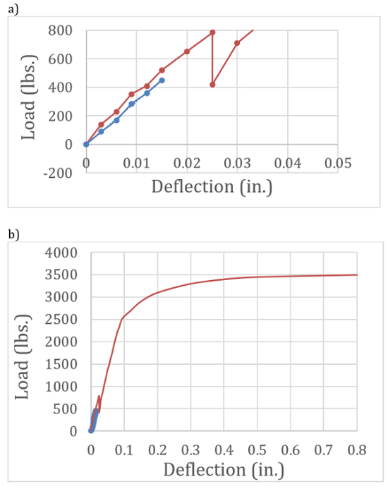
Figure 1: Comparison of load-deflection curves for unreinforced (blue) and reinforced (red) concrete beams at (a) small loads and (b) large loads (full curves).
Application and Summary
The test demonstrated the brittle nature of tensile failures in concrete and showed that the tensile strength is only a fraction (1/8 to 1/12) that of the compressive strength. Brittle failures of this type could have catastrophic consequences for human safety, and thus all concrete structures need to be reinforced with steel (or similar) bars to take tensile forces. A comparison of the load-deformation curve for the unreinforced and reinforced beams indicate not only that the latter possesses greater strength but also large deformation capacity.
The key to the safety and long-term performance of concrete structures is to provide steel reinforcement in areas of high tensile and shear stresses. In general, the amount of steel necessary to reach this goal is small, on the order of 1%-1.5% of the area of the concrete cross section. This small amount means that concrete structures can be economical, safe and provide good serviceability. In addition, the ability to cast concrete into any desired form gives architect great leeway in developing aesthetically pleasing structures.
Skip to...
Videos from this collection:

Now Playing
Tests of Hardened Concrete in Tension
Structural Engineering
23.5K Views

Material Constants
Structural Engineering
23.4K Views

Stress-Strain Characteristics of Steels
Structural Engineering
109.2K Views

Stress-Strain Characteristics of Aluminum
Structural Engineering
88.4K Views

Charpy Impact Test of Cold Formed and Hot Rolled Steels Under Diverse Temperature Conditions
Structural Engineering
32.1K Views

Rockwell Hardness Test and the Effect of Treatment on Steel
Structural Engineering
28.3K Views

Buckling of Steel Columns
Structural Engineering
36.1K Views

Dynamics of Structures
Structural Engineering
11.4K Views

Fatigue of Metals
Structural Engineering
40.5K Views

Tension Tests of Polymers
Structural Engineering
25.3K Views

Tension Test of Fiber-Reinforced Polymeric Materials
Structural Engineering
14.3K Views

Aggregates for Concrete and Asphaltic Mixes
Structural Engineering
12.1K Views

Tests on Fresh Concrete
Structural Engineering
25.7K Views

Compression Tests on Hardened Concrete
Structural Engineering
15.2K Views

Tests on Wood
Structural Engineering
32.9K Views
Copyright © 2025 MyJoVE Corporation. All rights reserved