
Magnetic Fields
Przegląd
Source: Yong P. Chen, PhD, Department of Physics & Astronomy, College of Science, Purdue University, West Lafayette, IN
Magnetic fields can be generated by moving charges, such as an electrical current. The magnetic field generated by a current can be calculated from the Maxwell equation. In addition, magnetic objects such as bar magnets can also generate magnetic fields due to microscopic dynamics of charges inside the material. Magnetic fields will exert magnetic force on other moving charges or magnetic objects, with the force proportional to the magnetic field. Magnetic fields are fundamental to electromagnetism and underlie many practical applications ranging from compasses to magnetic resonance imaging.
This experiment will demonstrate magnetic fields produced by a permanent bar magnet as well as an electrical current, using small compass needle magnets that align with magnetic fields. This experiment will also demonstrate the force exerted by the magnetic fields produced by a current on another current-carrying wire.
Zasady
Magnetic fields (commonly referred to as "B fields") can be produced by moving charges (such as an electrical current) or "permanent magnets" (such as common bar magnets) made of magnetic materials (such as iron). If one follows the local direction of the magnetic field to traces out the vector field lines, these lines (whose tangent reflects the local direction of magnetic field, and the density of the lines reflects the strength of the local magnetic field) are known as "magnetic field lines". They are fictitious lines that help visualize the distribution and direction of magnetic fields.
For example, a long straight wire carrying an electrical current I will produce a magnetic field in the surrounding space: the magnitude of the magnetic field is proportional to the current I and inversely proportional to the distance r from the wire; and the direction of the magnetic field (represented by "magnetic field lines") is along the circular tangent direction around the wire (determined by the so-called "right-hand rule", with the thumb pointing along the current and the fingers curling around the magnetic field direction), depicted in Figure 1a. A solenoid (made of many turns of current loops or coils) will produce a magnetic field that is also proportional to the current in the coil, and mostly uniform and along the long axis inside the solenoid (also determined by the right-hand rule, with fingers curling around the current and thumb pointing along the magnetic field), but spreads out and decays outside the solenoid (the magnetic field lines will return to the other end of the solenoid), depicted in Figure 1b. The magnetic field pattern produced by a bar magnet is similar to that by a solenoid, with the magnetic field lines leaving the north pole of the magnet and entering the south pole of the magnet, as depicted in Figure 1c.
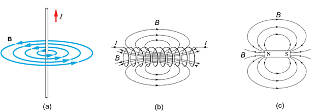
Figure 1: Diagram showing magnetic field patterns (visualized by magnetic field lines) generated by a straight-line current (a), a solenoid (b), and a bar magnet (c).
A magnetic field (B) will act on other magnetic objects and moving charges. A small bar magnet (such as a compass needle) placed in a magnetic field would tend to be aligned with the local magnetic field (meaning the south-north axis of the bar magnet is along the direction of the local magnetic field, which is also how the compass needle works to detect the direction of Earth's magnetic field). A magnetic field will exert a Lorentz force on a moving charge. The force is proportional to the local magnetic field (B), the charge (q), and its velocity (v), and points in a direction perpendicular to both the motion and the magnetic field. The Lorentz force vector (F) is proportional to the vector product between v and B and is given by:

Therefore, when F is zero, the direction of motion is parallel to the magnetic field but otherwise would bend the trajectory of the motion of the charge. Because of the Lorentz force, a magnetic field also exerts a force on a current carrying wire (as long as the current is not parallel to the direction of the magnetic field).
Procedura
1. Visualize Magnetic Field Lines
- Obtain a segment of straight conducting wire (at least several cm long), and a DC current source.
- Obtain a plate with a hole in the middle and several small compass needles on the plate, each mounted on a pin and freely rotatable.
- Feed the conducting wire through the hole so the straight section is perpendicular to the plate. Connect the conducting wire to the DC current source, as shown in Figure 2a. The connection can be made by cables with clamps.
- Turn on the current source and supply +5 A of current in the wire. Observe the behavior of the compass needles.
- Reverse the current to −5 A and observe the behavior of the compass needle again.
- Disconnect and remove the conducting wire and the current source. Obtain and bring a permanent bar magnet with its long-axis parallel to the board, to approach the plate from the side, with the north end of the magnet closer to the plate, as shown in Figure 2b. Observe the behavior of the compass needles.
- Flip the orientation of the bar magnet, with now its south end closer to the plate. Observe the behavior of the compass needles.
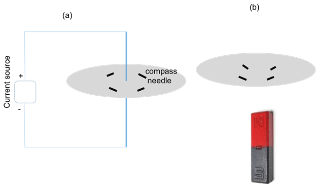
Figure 2: Diagram showing experimental setups using (a) a current flowing in a straight segment of wire that runs perpendicular to a plate and through the center hole on the plate; or (b) a bar magnet brought close to the plate and oriented perpendicular to the plate, to generate magnetic fields, which will orient compass needles on the plate along the direction of the local magnetic fields.
2. Effect of Magnetic Field
- Obtain two long and parallel conducting wires anchored on a framework, as shown in Figure 3a. If needed, one can use a wood frame with two parallel bars (top and bottom) and anchor or tape the two ends of the wires to the two bars.
- Use cables and clamps to connect the two wires in series and to the power source, with the top end of one wire connected to the bottom end of the other wire, as shown in Figure 3a.
- Turn on the power source so that current will flow in the same direction (flowing from top to bottom) in the two wires. Observe the two wires when the current is on.
- Turn off and disconnect the power source, now reconnect the two wires such that they are now connected again in series to the source, but with the top ends of the two wires shorted, as shown in Figure 3b.
- Now turn on the power source and observe that the current will flow through the two wires in opposite directions. Observe the two wires.

Figure 3: Diagram showing experimental setups of two parallel wires with current flowing in the same (a) or opposite (b) directions.
Wyniki
For steps 1.3-1.4, before the current is switched on, the compass needles are oriented randomly. After switching on the current, which flows in the wire from top to bottom, the compass needles will align themselves with the local magnetic field in a circular pattern, as depicted in Figure 4a (top view). Upon reversing the current, the magnetic field reverses, as do the orientations of the compasses, as depicted in Figure 4b.
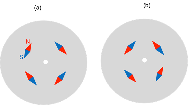
Figure 4: Diagram showing representative patterns of the compass needles responding to the current-induced magnetic fields (a) when the current is positive as shown in the setup shown in Figure 2a, where the current flows from top to bottom, and (b) when the current reverses (now from bottom to top).
For steps 1.6-1.7, the compass needles will orient themselves along the local magnetic fields created by the bar magnet (whose magnetic field pattern is shown in Figure 1c). Figure 5a (and 5b) depicts the representative pattern of the compass needles when the north (or south) end of the magnet is closer to the plate. Note that when the polarity of the bar magnet reverses, so does the magnetic field it creates, and so do the orientations of all compass needles.

Figure 5: Diagram showing representative patterns of the compass needles responding to the magnetic fields generated by the bar magnet (a) in the setup shown in Figure 2b, with the north pole of the magnet closer to the plate; and (b) with reversed polarity, with the south pole of the magnet closer to the plate.
For Section 2, the two wires will be seen to attract to each other when the currents flowing in them have the same direction, and repel each other when the currents in them have opposite directions. This is due to the Lorentz force of the magnetic field generated by one current acting on the other current-carrying wire. For the situation in Figure 3a (currents in two wire have same direction), the magnetic field (B) produced by the left wire is pointing into the page at the position of the right wire (according to the right hand rule, as well as in Figure 4b), and therefore the Lorentz force as determined by the vector product of qv (along the current direction) and B will point to the left (thus attractive). The force reverses (pointing to the right, thus repulsive) for the situation in Figure 3b, when the current in the right wire reverses (qv reverses). The directions of the force due to the magnetic field created by left wire acting on the right wire are depicted by red arrows in Figure 3.
Wniosek i Podsumowanie
In this experiment, we have visualized magnetic fields using compass needles that orient with the local magnetic field. We also demonstrated the Lorentz force of a magnetic field produced by a current on another nearly parallel current.
Magnetic fields play important roles in our everyday life and technology. They are generated by commonly used bar magnets or "kitchen magnets" as well as electromagnets (solenoids), and are used to pick up other magnetic objects. Earth also generates a magnetic field and that is how a compass needle (which aligns with the local magnetic field) is used to tell the direction (note the magnetic south pole of the earth as a magnet is actually close to the geographic north pole, such that the magnetic field on the earth surface points toward the geographic north direction). Magnetic resonance imaging (MRI), an important diagnostic tool in medicine, also needs a strong magnetic field to operate.
The author of the experiment acknowledges the assistance of Gary Hudson for material preparation and Chuanhsun Li for demonstrating the steps in the video.
Tagi
Przejdź do...
Filmy z tej kolekcji:

Now Playing
Magnetic Fields
Physics II
33.6K Wyświetleń

Electric Fields
Physics II
77.5K Wyświetleń

Electric Potential
Physics II
105.0K Wyświetleń

Electric Charge in a Magnetic Field
Physics II
33.7K Wyświetleń

Investigation Ohm's Law for Ohmic and Nonohmic Conductors
Physics II
26.2K Wyświetleń

Series and Parallel Resistors
Physics II
33.2K Wyświetleń

Capacitance
Physics II
43.8K Wyświetleń

Inductance
Physics II
21.6K Wyświetleń

RC/RL/LC Circuits
Physics II
142.9K Wyświetleń

Semiconductors
Physics II
29.9K Wyświetleń

Photoelectric Effect
Physics II
32.7K Wyświetleń

Reflection and Refraction
Physics II
36.2K Wyświetleń

Interference and Diffraction
Physics II
91.2K Wyświetleń

Standing Waves
Physics II
49.8K Wyświetleń

Sound Waves and Doppler Shift
Physics II
23.5K Wyświetleń
Copyright © 2025 MyJoVE Corporation. Wszelkie prawa zastrzeżone