
DC/DC Buck Converter
Przegląd
Source: Ali Bazzi, Department of Electrical Engineering, University of Connecticut, Storrs, CT.
While it is simple to step up or down AC voltages and currents using transformers, stepping up or down DC voltages and currents in an efficient and regulated manner requires switching power converters. The DC/DC buck converter chops the input DC voltage using a series input switch, and the chopped voltage is filtered through the L-C low-pass filter to extract the average output voltage. The diode provides a path for the inductor current when the switch is off for part of the switching period. The output voltage is this less than or equal to the input voltage.
The objective of this experiment is to study different characteristics of a buck converter. The step-down capability of the converter will be observed under continuous conduction mode (CCM) where the inductor current is non-zero. Open-loop operation with a manually-set duty ratio will be used. An approximation of the input-output relationship will be observed.
Zasady
Linear regulators (series and shunt) can provide step-down capability, but are highly inefficient when the output-to-input voltage ratio is very low. Voltage dividers can also step down DC voltage, however, there is no regulation involved with variable loads. Buck converters thus present efficient and robust DC voltage step-down capabilities.
In order to construct a buck-converter, we can start with the circuit shown below in Fig. 1(a). When the switch is on for a portion (D) of the switching period (T), the output voltage (Vo) and input voltage (Vin) are equal. When the switch is off for a portion (1-D) of the period, the output voltage is zero. This produces a square-wave output voltage whose average (shown by brackets < >) is less than that of the input voltage: <Vo>=VoD+ Vo(1-D)= VinD + 0(1-D)= VinD.
In order to minimize the output current ripple, and thus the output voltage ripple with a resistive load, an inductor is added as shown in Fig. 1(b). The issue with an inductor is that it maintains current flow until all its stored energy is released, so if the switch turns off, a large dI/dt will occur across the switch since current has to flow. Therefore, a freewheeling diode is added to provide an inductor current path as shown in Fig. 1(c). However, the inductor's inductance will have to be very large in order to have very low output voltage ripple, and a capacitor must be added to reduce the inductor size and provide a clean DC voltage output at the load as shown in Fig. 1(d).
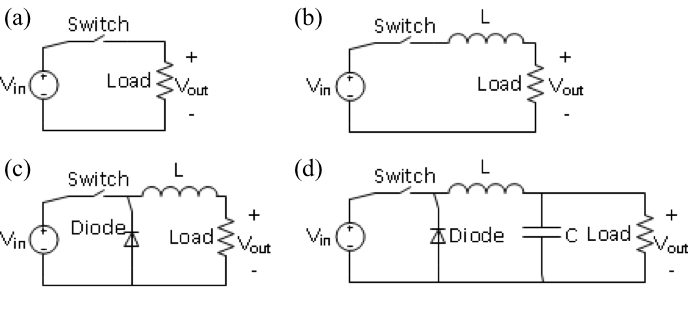
Figure 1. Steps to building a buck converter
As this experiment proceeds, it will be shown that the average output voltage will increase as the duty cycle, D, increases. With higher switching frequencies, the voltage ripple at the output will decrease since the voltage charging and discharging times at the capacitor become significantly shorter with a decreased switching frequency.
Procedura
This experiment will utilize the DC-DC converter board provided by HiRel Systems. http://www.hirelsystems.com/shop/Power-Pole-Board.html
Information about the board operation can be found in this collections video “Introduction to the HiRel Board.”
The procedure shown here applies to any simple buck converter circuit that can be built on proto boards, bread boards, or printed circuit boards.
1. Board setup
- Connect the ±12 signal supply at the "DIN" connector but keep "S90" OFF.
- Make sure that the PWM control selector is in the open-loop position.
- Set the DC power supply at 24 V. Keep the output disconnected from the board.
- Before connecting the load resistor, adjusted it to 12 Ω.
- Build the circuit shown in Fig. 2 by using the upper MOSFET, lower diode, and BB magnetic board. Record the inductance value shown in the board. Note that the BB magnetic board has an inductor with two terminals that plug in to the DC-DC converter (power-pole) board.
- Connect "RL"across "V2+" and "COM."
- Make sure the switch array for MOSFET selection, PWM selection, and other settings are as shown in Fig. 2.

Figure 2. Buck converter circuit
2. Adjusting the Duty Ratio and Switching Frequency
- Connect the differential probe across the gate to source of the upper MOSFET.
- Turn ON "S90." A switching signal should appear on the oscilloscope screen.
- Adjust the signal time axis to see two or three periods.
- Adjust the frequency potentiometer to achieve a frequency of 100 kHz (period of 10µs).
- Adjust the duty ratio potentiometer to achieve a 50% duty ratio.
3. Buck Converter Testing for Variable Input
- Connect the input DC power supply, which is already set at 24 V, to "V1+" and "COM."
- Connect the differential probe across the gate to source of the upper MOSFET.
- Connect the other probe across the load. Make sure the ground connector is connected to "COM."
- Capture the waveforms and measure the output voltage mean and on-time of the gate-to-source voltage (also the duty ratio).
- Record the input current and voltage readings on the DC power supply.
- Adjust the input voltage to 21 V, 18 V and 15 V, and repeat the above steps for each of these voltages.
- Disconnect the input DC supply and adjust its output to 24 V.
4. Buck Converter Testing for Variable Duty Ratio
- Connect the differential probe across the gate to source of the upper MOSFET.
- Connect the other probe across the load. Make sure the ground connector is connected to "COM."
- Connect the input DC supply that is set to 24 V between "V1+" and "COM."
- Capture the waveforms and measure the output voltage mean and on-time of the gate-to-source voltage (also the duty ratio).
- Record the input current and voltage readings on the DC power supply.
- Adjust the duty ratio for three steps of your choice between 30% and 70%. Repeat the above steps for each of these three duty ratios.
- Reset the duty ratio to 50%.
- Disconnect the input DC supply.
5. Buck Converter Testing for Variable Switching Frequency
- Connect the differential probe across the gate to source of the upper MOSFET.
- Connect the other probe across the load. Make sure the ground connector is connected to "COM."
- Connect the input DC supply to "V1+" and "COM."
- Capture the waveforms and measure the output voltage mean and on-time of the gate-to-source voltage (also the duty ratio).
- Record the input current and voltage reading on the DC power supply.
- Adjust the switching frequency for three steps of your choice between 5 kHz and 40 kHz. Repeat the above steps for each of these three duty ratios.
- Turn OFF the input DC supply and "S90," and then disassemble the circuit.
Wyniki
It is expected the output-input voltage relationship of an ideal buck converter to be related to the duty cycle or duty ratio D. If the input voltage is Vin and the output voltage is Vout, Vout/Vin = D, where 0≤D≤ 100%. Therefore, for an input voltage of 24 V, Vout≈ 12 V for D = 50%, Vout≈ 7.2 V for D = 30%, and Vout≈ 16.8 V for D = 70%. Nevertheless, the output voltage will be lower than expected from the ideal relationship, which is linear with the duty ratio, and the main reason is that the ideal buck converter model does not account for non-idealities and voltage drops in the converter.
Wniosek i Podsumowanie
Buck converters are very common in electronic device chargers where they provide excellent voltage regulation required for battery charging. They are commonly used in power supplies that power computers, integrated circuits and electronic boards, as well as in renewable energy applications and battery fed systems.
Przejdź do...
Filmy z tej kolekcji:

Now Playing
DC/DC Buck Converter
Electrical Engineering
21.1K Wyświetleń

Electrical Safety Precautions and Basic Equipment
Electrical Engineering
144.6K Wyświetleń

Characterization of Magnetic Components
Electrical Engineering
15.0K Wyświetleń

Introduction to the Power Pole Board
Electrical Engineering
12.4K Wyświetleń

DC/DC Boost Converter
Electrical Engineering
56.9K Wyświetleń

Flyback Converter
Electrical Engineering
13.2K Wyświetleń

Single Phase Transformers
Electrical Engineering
20.1K Wyświetleń

Single Phase Rectifiers
Electrical Engineering
23.4K Wyświetleń

Thyristor Rectifier
Electrical Engineering
17.5K Wyświetleń

Single Phase Inverter
Electrical Engineering
17.9K Wyświetleń

DC Motors
Electrical Engineering
23.4K Wyświetleń

AC Induction Motor Characterization
Electrical Engineering
11.6K Wyświetleń

VFD-fed AC Induction Machine
Electrical Engineering
6.9K Wyświetleń

AC Synchronous Machine Synchronization
Electrical Engineering
21.6K Wyświetleń

AC Synchronous Machine Characterization
Electrical Engineering
14.2K Wyświetleń
Copyright © 2025 MyJoVE Corporation. Wszelkie prawa zastrzeżone